Download
1 / 25
250 likes | 275 Vues
Learn about latches, flip-flops, clocking methods, storage elements, and how sequential circuits function. Dive into synchronous and asynchronous circuits to grasp state changes and outputs. Explore the basics, master the concepts, and improve your understanding.

E N D
Sequential Circuits : Part I Read Sections 5-1, 5-2, 5-3
Topics • Sequential Circuits • Latches • Flip Flops
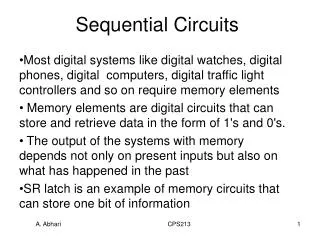
Sequential Circuits • Definition: State of system is “stored information” • Present state and inputs, determine outputs and next state
Types of Sequential Circuits • Synchronous • State changes are synchronized by one or more clocks • Asynchronous • Each state change occurs independently of other changes
Clocking of Synchronous • Changes of the state enabled by a clock
Comparison • Synchronous • Easier to analyze • Choose the clock so that changes are only allowed to occur before next clock pulse • Asynchronous • Potentially faster • Harder to analyze • Will look mostly at synchronous
YES.YESYESYESYESYESYESYESYESYESYESYES YES.YESYESYESYESYESYESYESYESYESYESYES YES.YESYESYESYESYESYESYESYESYESYESYES YES.YESYESYESYESYESYESYESYESYESYESYES YES.YESYESYESYESYESYESYESYESYESYESYES YES.YESYESYESYESYESYESYESYESYESYESYES YES.YESYESYESYESYESYESYESYESYESYESYES YES.YESYESYESYESYESYESYESYESYESYESYES YES.YESYESYESYESYESYESYESYESYESYESYES YES.YESYESYESYESYESYESYESYESYESYESYES YES.YESYESYESYESYESYESYESYESYESYESYES ____________________________________ Fig. 5-2 Logic Structures for Storing Information Basic Storage
YES.YESYESYESYESYESYESYESYESYESYESYES YES.YESYESYESYESYESYESYESYESYESYESYES YES.YESYESYESYESYESYESYESYESYESYESYES YES.YESYESYESYESYESYESYESYESYESYESYES YES.YESYESYESYESYESYESYESYESYESYESYES YES.YESYESYESYESYESYESYESYESYESYESYES ____________________________________ Fig. 5-2 Logic Structures for Storing Information Basic Storage • Apply low or high for longer than tpd • Feedback will hold the value of the input
____________________________________ Fig. 5-2 Logic Structures for Storing Information Basic Storage • Apply low or high for longer than tpd • Feedback will hold the value of the input
Fig. 5-4 SR Latch with NOR Gates SR (set-reset) Latches • Basic storage made from gates • Requirement: outputs be the complements of each other • S & R both 0, Latch in “resting” state • Have to keep both from 1 at same time
When both S and R go to 0 after 11, Q & Q_b take on unknown values; depends on circuit delays and slight differences in the times at which S & R change values Simulation Of SR Behavior
YES. yes. YES.YES.YES.YES.YES. YES YES. YES. yes. YES.YES.YES.YES.YES. YES YES. YES. yes. YES.YES.YES.YES.YES. YES YES. Latch
Good Morning. Good Morning. Good Morning. Good Morning Add Control Input (SR ) • Input, C, controls when state can change
Add Control Input (SR ) • Input, C, controls when state can change • Is there a latch with no undefined state?
D-type Latch • No undefined (illegal) state
D-type Latch • No undefined (illegal) state
Flip-Flops • Two major types • Master-Slave • Two stage • Output not changed until clock disabled (low) • Edge triggered • Change happens when clock level changes
Master Latch Slave Latch Master-Slave Flip-Flop • Either master or slave is enabled, not both
Illegal State (a) Q should be 0 since Q was 0 before the clock pulse and both S & R are 0 just before the clock goes to 0 (b) FF in wrong state due to 1’s catching Timing Diagram
Note: • New inputs appear at latches are not sent to output until clock low • Changes at input of FF when clock high trigger next state
Standard Symbols for Storage Elements S S D D R R C C D with 0 Control SR D with 1 Control SR (a) Latches S S D D C C R R C C Triggered D Triggered D Triggered SR Triggered SR (b) Master-Slave Flip-Flops D D C C Triggered D Triggered D (c) Edge-Triggered Flip-Flops • Master-Slave:Postponed outputindicators • Edge-Triggered:Dynamicindicator
Direct Inputs • Set/Reset independent of clock • Direct set or preset • Direct reset or clear • Often used for power-up reset
Next • State Diagrams • Registers