Download
1 / 69
750 likes | 1.11k Vues
Synchronous Sequential Logic. Chapter 5. Sequential Circuits. Combinational circuits + storage (store binary information) Binary information stored defines the state of the sequential circuit

E N D
Synchronous Sequential Logic Chapter 5
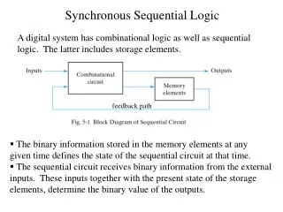
Sequential Circuits • Combinational circuits + storage (store binary information) • Binary information stored defines the state of the sequential circuit • External input + present state determine the binary value of outputs and change state in storage elements
Sequential Circuits Block diagram of a sequential circuit
Sequential Circuits • Synchronous sequential circuit is a system whose behavior can be defined from the knowledge of its signals at discrete instants of time • Asynchronous sequential circuit is a system whose behavior depends on the input signals at any instant of time and the order in which the inputs change
Storage elements in synchronous sequential circuits • Latches: Operate on signal levels • Level-sensitive devices • Flip-Flops: Controlled by a clock transition • Edge-sensitive devices • Latches are the basic circuits from which all flip-flops are constructed
Sequential Circuits Synchronous clocked sequential circuit
Storage Elements: Latches What do you observe in this circuit? Exercise: Group discussion. Suppose that Q=1 and Q’=0. What happens with the circuit if S is set to 1 and R is set to 0? What happens if S and R are both set to 0? What happens if S is set to 0 and R is set to 1? What happens if S and R are both set to 0? What happens if S and R are both set to 1?
Storage Elements: Latches Set state Reset state SR latch with NOR gates
Storage Elements: Latches Exercise: Group discussion. Suppose that Q=1 and Q’=0. What happens with the circuit if S is set to 1 and R is set to 0? What happens if S and R are both set to 1? What happens if S is set to 0 and R is set to 1? What happens if S and R are both set to 1? What happens if S and R are both set to 0?
Storage Elements: Latches Reset state Set state SR latch with NAND gates or R’S’ latch
Storage Elements: Latches Exercise: Group discussion. Suppose that Q=1 and Q’=0. What happens with the circuit if S is set to 1, R is set to 0 and ? What happens with the circuit if S is set to 1, R is set to 0 and ? What happens if S is set to 0, R is set to 1 and ? What happens if S is set to 0, R is set to 1 and ? What does do?
Storage Elements: Latches SR latch with control input
Storage Elements: Latches Compare these two latches. What advantage(s) could have one over the other?
D latch (transparent latch) D latch
Storage Elements: Latches Graphic symbols for latches
Storage Elements: Flip-Flops Latch Trigger Flip-Flop Compare the two types of trigger signals. Clock response in Latch and Flip-Flop
Storage elements: Flip-Flops Master-slave D flip-flop Analyze the operation of this circuit. Assume initially Q=0, D=1, Clk=0. What happens when Clk changes to 1? What happens while Clk remains at 1? What happens when Clk changes to 0?
Other edge-triggered D flip-flop Discuss with your neighbor classmate the operation of this circuit. Assume some initial conditions. D-type positive-edge-triggered flip-flop
Edge-triggered D flip-flop Graphic symbol for edge-triggered D flip-flop
Other flip-flops JK flip-flop Let be the state of output at time . Analyze what happens to the output at time for all the different combinations of the and inputs. Use the table on the following slide.
Table for the analysis of flip-flop For the analysis of the flip-flop fill in the following table. Input function to D flip-flip input:
Other flip-flops T flip-flop (Toggle) Fill in the following table for the Toggle flip-flop
Direct inputs D flip-flop with asynchronous reset 1 1
Characteristic equations • Describe logical properties of a flip-flop, just like a characteristic table, e.g.: • For a D flip-flop: • For a JK flip-flop: , and • For a T-flip-flop:
Analysis of Clocked Sequential Circuits • Describes what a circuit will do under certain operating conditions • Behavior depends on inputs, outputs, and the state of flip-flops • Outputs are function of inputs and present state • Analysis obtains a table or diagram for the time sequence of inputs, outputs and internal states, and includes time sequence
State table • Exercise: Compare tables 5.2 and 5.3. What makes the difference? • Compare any of the state tables (5.2 or 5.3) with the state equations. How do you relate equations and table? How do you obtain one from the other?
State diagram 0/0 1/0 00 0 10 1 0/1 0/1 1/0 0/1 1/0 01 0 11 1 1/0
Flip-flops input equations Input equations Output equation
Analysis of circuits with flip-flops State table has four sections:
Analysis of circuits with flip-flops • Determine the flip-flop input equations in terms of the present state and input variables • List the binary values of each input equation • Use the corresponding flip-flop characteristic table to determine the next-state values in the state table
Analysis with JK flip-flops Input equations
Analysis with JK flip-flops Substituting the values of and for , and and we obtain:
Analysis with T flip-flops Characteristic equation of T flip-flop Input Equations Output Equations State Equations
State Reduction and Assignment • Analysis of sequential circuit starts with circuit and finishes with state table or diagram • Design starts with state table or diagram • State reduction aims at exhibiting the same input-output behavior but with a lower number of internal states • Fewer internal states leads to fewer flip-flops • May lead to use more gates
State reduction An infinite number of input sequences can be applied to a circuit, for example, the one whose state diagram is shown
Algorithm for state reduction • Two states are said to be equivalent if: • For each member of the set of inputs they give exactly the same output and send the circuit to either • The same state or • An equivalent state • When two states are equivalent, one of them can be removed
State reduction Change g by e, which is the equivalent state Exercise: go through Table 5.6 and try to find equivalent states applying the algorithm described before.