Download

1 / 10
150 likes | 516 Vues
SYNCHRONOUS SEQUENTIAL CIRCUITS. Introduction Huffman Model Sequence Detector Moore Machine Mealy Machine One Hot and One Cold Implementation Handshaking Designing a Garage Door Opener Shift Register Sequential Multiplier. Introduction.

E N D
SYNCHRONOUS SEQUENTIAL CIRCUITS Introduction Huffman Model Sequence Detector Moore Machine Mealy Machine One Hot and One Cold Implementation Handshaking Designing a Garage Door Opener Shift Register Sequential Multiplier
Introduction Since now what we have done is how to build a circuit that does an especial task for us, not important when the task was done, Data-path, But now we want to focus on when the task will be done, Controller. We start our discussion with a sequence detector. So the steps will be Problem Description State diagram State table State assignment Transition table Flip-flop type Excitation table Karaugh map Circuit
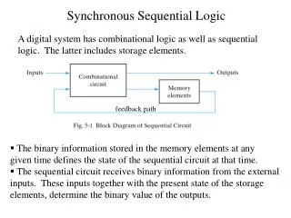
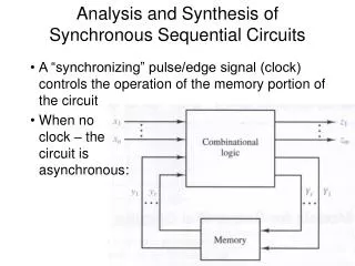
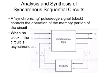
Huffman Model • The model we will be using in which everything happening is synchronized to a clock that is implicitly part of our circuit is called the Huffman Model as seen in the following figure Each sequential circuit that you will see has a combinational part and a register part where the register part feedbacks its output to the combinational part. What we need to be able to design such circuits with practical speed is a straight forward method.
Sequence Detector • As our first design we will see a 110 detector that will give a high output whenever clocked with such a sequence on its input. Obviously such a circuit is sequential because its output relies on a series of certain inputs in its history. To do our circuit design of this problem we start from its state diagram. We may even not know how many states we need but we work our way through the different states. In synchronous sequential circuits such as that of this problem, anything happening when the clock is in its active state. When doing our design of sequential circuits we consider the clock pulse to be implicit and no gating must be done on this signal.
Moore Machine • This problem can be the same as looking for a special sequence of shops when walking along a road. Consider you are looking for 2 book shops followed by a grocery store. Now if we see a grocery store first we simply ignore it (meaning that we stay in our initial state), but seeing a book shop we will need to remember that we have passed the first shop we were looking for in that special sequence (meaning that we change to a new state). • The same method can be applied to our problem, where seeing a 0 is seeing a grocery store and a 1 is a book shop. Thus as we saw above seeing a 0 first must not change our state and so on. Applying this method to our problem gives the following state diagram In our flow of design the only part that doesn’t actually involve mechanical steps is the drawing of the problem’s state diagram.
Moore Machine ( cont. ) • We saw the state diagram, now we want to work through a couple more states to be able to find the circuit itself. • First we change the state diagram to a tabular form as shown in this figure. This table is called a state table that nears the state diagram to tables we saw before, such as the Karaugh map etc. • The next step of our synthesis is a decision that has to be made about the type of flip flop we want to use. • Because of the 4 states we have we will need 2 feedback lines (referring to the Huffman model) and this means 2 flip flops with one clock on them. Ultimately we need a form of this table that can be mapped in a Karnaugh Map. To do this we naturally need to replace the state names with numbers. We can use binary state assignment, where a unique binary number is used to represent each state. x x Until now we haven’t ever talked about having a clock explicitly. But it can be implied from the fact that we have referred to a next state. 00 01 11 10 transition table (next state)
Moore Machine ( cont. ) Static flip flops can be used with any frequency less than the maximum which is decided considering the above mentioned, but when we are using dynamic flip flops we also need to be concerned about a minimum frequency, because data may be lost if we do not refresh the transistors in time. • The stage that was mentioned(after choosing a particular flip flop) is to form an excitation table considering that particular flip flop in order to reach a stage where we can move what we’ve had so far to a Karnaugh Map. • If we choose a D flip flop Q+=D Let’s consider a state where a hazard may occur in the point marked ‘*’ in the circuit of the last example. Reality has it that we needn’t worry about this happening because it can be easily solved by setting the clock frequency to work on the worst case delay and thus after any hazards that may occur in such parts of a circuit. • Considering the Huffman model and the fact that we have now the excitation tables for the flip flop inputs we can find the glue logic needed before the inputs of the flip flops. This is done by mapping the data in the excitation table on a Karnaugh Map for D1 and D0 x x 0 1 0 1 00 01 11 10 00 01 11 10 0 1 0 1 = x w = . = x. + .
Mealy Machine • If we relax timing issues a little in our design, another sate machine that can be more minimal can be used. In this machine called the Mealy Machine, the output is dependent on input changes and thus is no longer synchronized to the clock. • The following is the Mealy machine for the 011 detector. The output changes to 1 as soon as the 0 of the sequence is seen. x x x TransitionTable State Table x x x x 0 1 0 1 0 1 00 01 11 10 00 01 11 10 00 01 11 10 out-put out-put = x w = . = x.
Mealy Machine ( cont. ) In some cases, relaxing time issues of the problem and using Mealy machines can help a lot in less hardware use. The contribution of the input signal to the output in Mealy machines means less precision because any hazard on the input (noise, hazards from the levels before etc) can easily propagate onto the output. Because of such problems, Mealy machines can be never used in very precise designs.
Mealy Machine ( cont. ) In synchronous sequential circuits we only care about the output’s value on clock pulses and we don’t care about its value at instances in between. Another thing to be mentioned is that Mealy machine gives the output one clock cycle earlier. • The following timing diagram shows the differences in the two state machines output very clearly. The contribution of the input on the output can be seen in the timing diagram as well