Download

1 / 62
630 likes | 657 Vues
CHAPTER 6 PASS-BAND DATA TRANSMISSION. 6.1. Introduction 6.2. Pass-band Transmission 6.3 Coherent Phase Shift Keying - BPSK. Outline.

E N D
CHAPTER 6PASS-BAND DATA TRANSMISSION Digital Communication Systems 2012 R.Sokullu
6.1. Introduction 6.2. Pass-band Transmission 6.3 Coherent Phase Shift Keying - BPSK Outline Digital Communication Systems 2012 R.Sokullu
In Ch. 4 we studied digital baseband transmission where the generated data stream, represented in the form of discrete pulse-amplitude modulated signal (PAM) is transmitted directly over a low-pass channel. In Ch.6 we will study digital pass-band transmission where the incoming digital signal is modulated onto a carrier (usually sinusoidal) with fixed frequency limits imposed by the band-pass channel available The communication channel used in pass-band digital transmission may be microwave radio link, satellite channel etc. Other aspects of study in digital pass-band transmission are line codes design and orthogonal FDM techniques for broadcasting. 6.1 Introduction Digital Communication Systems 2012 R.Sokullu
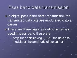
The modulation of digital signals is a process involving switching (keying) the amplitude, frequency or phase of a sinusoidal carrier in some way in accordance with the incoming digital data. Three basic schemes exist: amplitude shift keying (ASK) frequency shift keying (FSK) phase shift keying (PSK) REMARKS: In continuous wave modulation phase modulated and frequency modulated signals are difficult to distinguish between, this is not true for PSK and FSK. PSK and FSK both have constant envelope while ASK does not. Definitions: Digital Communication Systems 2012 R.Sokullu
Figure 6.1Illustrative waveforms for the three basic forms of signaling binary information. (a) Amplitude-shift keying. (b) Phase-shift keying. (c) Frequency-shift keying with continuous phase. Digital Communication Systems 2012 R.Sokullu
Depending on whether the receiver does phase-recovery or not the modulation techniques are divided into: Coherent Non-coherent Phase recovery circuit - ensures synchronization of locally generated carrier wave (both frequency and phase), with the incoming data stream from the Tx. Binary versus M-ary schemes binary – use only two symbol levels; M-ary schemes – pure M-ary scheme exists as M-ary ASK, M-ary PSK and M-ary FSK, using more then one level in the modulation process; Also hybrid M-ary schemes – quadrature-amplitude modulation (QAM); preferred over band-pass transmissions when the requirement is to preserve bandwidth at the expense of increased power Hierarchy of Digital Modulation Techniques Digital Communication Systems 2012 R.Sokullu
Linearity M-ary PSK and M-ary QAM are both linear modulation schemes; M-ary PSK – constant envelope; M-ary QAM – no M-ary PSK – used over linear channels M-ary QAM – used over non-linear channels Coherence ASK and FSK – used with non-coherent systems; no need of maintaining carrier phase synchronization “noncoherent PSK” means no carrier phase information; instead pseudo PSK = differential PSK (DPSK); Remarks: Digital Communication Systems 2012 R.Sokullu
Design goal – minimize the average probability of symbol error in the presence of AWGN. Signal-space analysis is a tool for setting decision areas for signal detection over AWGN (i.e. based on maximum likelihood signal detection) (Ch.5!) Based on these decisions probability of symbol error Pe is calculated for simple binary coherent methods as coherent binary PSK and coherent binary FSK, there are exact formulas for Pe for coherent M-ary PSK and coherent M-ary FSK approximate solutions are sought. Probability of Error Digital Communication Systems 2012 R.Sokullu
power spectra of resulting modulated signals is important for: comparison of virtues and limitations of different schemes study of occupancy of channel bandwidth study of co-channel interference Power Spectra Digital Communication Systems 2012 R.Sokullu
A modulated signal is described in terms of in-phase and quadrature component as follows: complex envelope Digital Communication Systems 2012 R.Sokullu
The complex envelope is actually the baseband version of the modulated (bandpass) signal. • sI(t) and sQ(t) as components of are low-pass signals. Let SB(f) denote the power spectral density of the complex envelope , known as baseband power spectral density. The power spectral density Ss(f) of the original band-pass signal s(t) is a frequency shifted version of SB(f) except for a scaling factor: Digital Communication Systems 2012 R.Sokullu
So, • as far as the power spectrum is concerned it is sufficient to evaluate the baseband power spectraldensity SB(f) and since is a low-pass signal, the calculation of SB(f) should be simpler than the calculation of Ss(f). Digital Communication Systems 2012 R.Sokullu
Main goal of communication engineering – spectrally efficient schemes maximize bandwidth efficiency = ratio of the data rate in bits per seconds to the effectively utilized channel bandwidth. achieve bandwidth at minimum practical expenditure of average SNR Bandwidth efficiency Digital Communication Systems 2012 R.Sokullu
The effectiveness of a channel with bandwidth B can be expressed as: bandwidth data rate Digital Communication Systems 2012 R.Sokullu
Before (Ch.4) we discussed that the bandwidth efficiency is the product of two independent factors: multilevel encoding – use of blocks of bits instead of single bits. spectral shaping – bandwidth requirements on the channel are reduced by the use of suitable pulse-shaping filters Digital Communication Systems 2012 R.Sokullu
6.1. Introduction 6.2. Pass-band Transmission 6.3 Coherent Phase Shift Keying Binary Phase shift Keying (BPSK) Quadriphase-Shift Keying (QPSK) Outline Digital Communication Systems 2012 R.Sokullu
6.2 Pass-band transmission model • Functional blocks of the model • Transmitter side • message source, emitting a symbol every T seconds; a symbol belongs to an alphabet of M symbols, denoted by m1, m2, ….mM; the a priori probabilities P(m1), P(m2),…P(mM) specify the message source output; when symbols are equally likely we can express the probability pi as: Digital Communication Systems 2012 R.Sokullu
signal transmission encoder , producing a vector si made up of N real elements, one such set for each of the M symbols of the source alphabet; dimension- wise N≤M; si is fed to a modulator that constructs a distinct signal si(t) of duration T seconds as the representation of symbol mi generated by the message source; the signal si is an energy signal (what does this mean?); si is real valued Channel: linear channel wide enough to accommodate the transmission of the modulated signal with negligible or no distortion the channel white noise is a sample function of AWGN with zero mean and N0/2 power spectral density Digital Communication Systems 2012 R.Sokullu
Receiver side (blocks described in detail p.326-327) detector signal transmission decoder; reverses the operations performed in the transmitter; Figure 6.2Functional model of pass-band data transmission system. Digital Communication Systems 2012 R.Sokullu
6.1. Introduction 6.2. Pass-band Transmission 6.3 Coherent Phase Shift Keying Binary Phase shift Keying(BPSK) Quadriphase-Shift Keying (QPSK) Outline Digital Communication Systems 2012 R.Sokullu
6.3 Coherent Phase Shift Keying- Binary Phase Shift Keying (BPSK) • In a coherent binary PSK the pair of signals used to represent binary 0 and 1 are defined as: duration of one bit fc=nc/Tb transmitted energy per bit Digital Communication Systems 2012 R.Sokullu
The equations (6.8) and (6.9) represent antipodal signals – sinusoidal signals that differ only in a relative phase shift of 180 degrees. • In BPSK there is only onebasis function of unit energy expressed as: • So the transmitted signals can be expressed as: Digital Communication Systems 2012 R.Sokullu
A coherent BPSK system can be characterized by having a signal space that is one dimensional (N= 1), with signal constellation consisting of two message points (M = 2) • The coordinates of the message points are: Digital Communication Systems 2012 R.Sokullu
Figure 6.3Signal-space diagram for coherent binary PSK system. The waveforms depicting the transmitted signals s1(t) and s2(t), displayed in the inserts, assume nc 2.Note that the frequency fc is chosen to ensure that each transmitted bit contains an integer number of cycles.. message point corresponding to s2 message point corresponding to s1 nc is an integer such that Tsymbol = nc/Tbit Digital Communication Systems 2012 R.Sokullu
Decision rule: based on the maximum likelihood decision algorithm/rule which in this case means that we have to choose the message point closest to the received signal point Error Probability of Binary PSK observation vector x lies in region Zi if the Euclidean distance ||x-sk|| is minimum for k = i • For BPSK: N= 1, space is divided into two areas (fig.6.3) • the set of points closest to message point 1 at +E1/2 • the set of points closest to message point 2 at – E1/2 Digital Communication Systems 2012 R.Sokullu
The decision rule is simply to decide that signal s1(t) (i.e. binary 1) was transmitted if the received signal point falls in region Z1, and decide that signal s2(t) (i.e. binary symbol 0) was transmitted if the received signal falls in region Z2. • Two kinds of errors are possible due to noise: • sent s1(t), received signal point falls in Z2 • sent s2(t), received signal point falls in Z1 • This can be expressed as: Zi: 0 < x1 < æ • and the observed element is expressed as a function of the received signal x(t) as: Digital Communication Systems 2012 R.Sokullu
So, • In Ch.5 it was deduced that memory-less AWGN channels, the observation elements Xi are Gaussian RV with mean sijand variance N0/2. • The conditional probability density function that xj(signal sj was received providing miwas sent) is given by: Digital Communication Systems 2012 R.Sokullu
When we substitute for the case of BPSK • Then the conditional probability of the receiver in favor of 1 provided 0 was transmitted is: Digital Communication Systems 2012 R.Sokullu
if we substitute and change the integration variable: Digital Communication Systems 2012 R.Sokullu
Considering an error of the second kind: • signal space is symmetric about the origin • p01 is the same as p10 • Average probability of symbol error or the bit error rate for coherent BPSK is: • So increasing the signal energy per bit makes the points - and move farther apart which correspond to reducing the error probability. Digital Communication Systems 2012 R.Sokullu
Transmitter side: Need to represent the binary sequence 0 and 1 in polar form with constant amplitudes, respectively – and + (polar non-return-to-zero – NRZ - encoding). Carrier wave is with frequency fc=(nc/Tb) Required BPSK modulated signal is at the output of the product modulator. Receiver side noisy PSK is fed to a correlator with locally generated reference signal correlator output is compared to a threshold of 0 volts in the decision device Generation and Detection of Coherent BPSK Signals Digital Communication Systems 2012 R.Sokullu
Figure 6.4Block diagrams for (a) binary PSK transmitter and (b) coherent binary PSK receiver. Digital Communication Systems 2012 R.Sokullu
Power Spectra of BPSK • From the modulator – the complex envelope of the BPSK has only in-phase component • Depending on whether we have a symbol 1 or 0 during the signaling interval 0 ≤ t ≤ Tb the in-phase component is +g(t) or – g(t). symbol shaping function Digital Communication Systems 2012 R.Sokullu
We assume that the input binary wave is random, with symbols 1 or 0 equally likely and that symbols transmitted during the different time slots are statistically independent. • So, (Ch.1) the power spectra of such a random binary wave is given by the energy spectral density of thesymbol shaping function divided by the symbol duration.(See Ex.1.3 and 1.6) • g(t) is an energy signal – FT • Finally, the energy spectral density is equal to the squared magnitude of the signals FT. Digital Communication Systems 2012 R.Sokullu
6.1. Introduction 6.2. Pass-band Transmission 6.3 Coherent Phase Shift Keying Binary Phase shift Keying (BPSK) Quadriphase-Shift Keying (QPSK) Outline Digital Communication Systems 2012 R.Sokullu
6.3 Coherent Phase Shift Keying - QPSK • Reliable performance • Very low probability of error • Efficient utilization of channel bandwidth • Sending more then one bit in a symbol • Quadriphase-shift keying (QPSK) - example of quadrature-carrier multiplexing • Information is carried in the phase • Phase can take one of four equally spaced values – π/4, 3π/4, 5π/4, 7π/4 • We assume gray encoding (10, 00, 01, 11) • Transmitted signal is defined as: Digital Communication Systems 2012 R.Sokullu
Signal-Space Diagram of QPSK • From 6.23 we can redefine the transmitted signal using a trigonometric identity: • From this representation we can use Gram-Schmidt Orthogonal Procedure to create the signal-space diagram for this signal. • It allows us to find the orthogonal basis functions used for the signal-space representation. Digital Communication Systems 2012 R.Sokullu
In our case there exist two orthogonal basis functions in the expansion of si(t). These are φ1(t) and φ2(t), defined by a pair of quadrature carriers: • Based on these representations we can make the following two important observations: Digital Communication Systems 2012 R.Sokullu
There are 4 message points and the associated vectors are defined by: • Values are summarized in Table 6.1 • Conclusion: • QPSK has a two-dimensional signal constellation (N = 2) and four message points (M = 4). • As binary PSK, QPSK has minimum average energy Digital Communication Systems 2012 R.Sokullu
Figure 6.6Signal-space diagram of coherent QPSK system. Digital Communication Systems 2012 R.Sokullu
Generate a QPSK signal for the given binary input. Input binary sequence is: 01101000 Divided into odd- even- input bits sequences Two waveforms are created: si1φ1(t) and si2 φ2(t) – individually viewed as binary PSK signals. By adding them we get the QPSK signal Example 6.1 Digital Communication Systems 2012 R.Sokullu
To define the decision rule for the detection of the transmitted data sequence the signal space is partitioned into four regions in accordance with: Example 6.1 – cont’d observation vector x lies in region Zi if the Euclidean distance ||x-sk|| is minimum for k = i • Result: Four regions – quadrants – are defined, whose vertices coincide with the origin. • Marked in fig. 6.6 (previous pages) Digital Communication Systems 2012 R.Sokullu
Figure 6.7(a) Input binary sequence. (b) Odd-numbered bits of input sequence and associated binary PSK wave. (c) Even-numbered bits of input sequence and associated binary PSK wave. (d) QPSK waveform defined as s(t) si1f1(t) si2f2(t). Digital Communication Systems 2012 R.Sokullu
Error probability of QPSK • In a coherent system the received signal is defined as: • w(t) is the sample function of a white Gaussian noise process of zero mean and N0/2. Digital Communication Systems 2012 R.Sokullu
The observation vector has two elements, x1 and x2, defined by: Digital Communication Systems 2012 R.Sokullu
The observation vector has two elements, x1 and x2, defined by: i=1 and 3 so cos(π/4) = 1/2 Digital Communication Systems 2012 R.Sokullu
i=2 and 4 so sin(3π/4) = 1/2 Digital Communication Systems 2012 R.Sokullu
The observable elementsx1 and x2 are sample values of independent Gaussian RV with mean equal to +/-√E/2 and -/+√E/2 and variance equal to N0/2. The decision rule is to find whether the received signal si is in the expected zone Zi or not. So, Digital Communication Systems 2012 R.Sokullu
QPSK is actually equivalent to two BPSK systems working in parallel and using carriers that are quadrature in phase. According to 6.29 and 6.30 these two BPSK are characterized as follows: The signal energy per bit is √E/2 The noise spectral density is N0/2. Calculate the average probability of bit error for each channel as: Calculation of the error probability: Digital Communication Systems 2012 R.Sokullu