Download
1 / 116
1.31k likes | 1.99k Vues
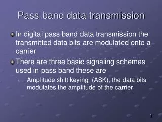
Pass-band Data Transmission. Dr. Teerasit Kasetkasem. Block Diagram. Functional model of pass-band data transmission system. Signaling .

E N D
Pass-band Data Transmission Dr. Teerasit Kasetkasem
Block Diagram • Functional model of pass-band data transmission system.
Signaling • Illustrative waveforms for the three basic forms of signaling binary information. (a) Amplitude-shift keying. (b) Phase-shift keying. (c) Frequency-shift keying with continuous phase.
What do we want to study? • We are going to study and compare different modulation techniques in terms of • Probability of errors • Power Spectrum • Bandwidth efficiency Bits/s/Hz
Coherent PSK • Binary Phase Shift Keying (BPSK) • Consider the system with 2 basis functions • and
s0 s1 s0 We place s0 to minimize probability of error BPSK • If we want to fix that for both symbols (0 and 1) the transmitted energies are equal, we have 2 1
s1 s0 BPSK • We found that phase of s1and s0 are 180 degree difference. We can rotate s1and s0 2 1 Rotate
s1 s0 BPSK • We observe that 2 has nothing to do with signals. Hence, only one basis function is sufficient to represent the signals 2 1
BPSK • Finally, we have
BPSK • Signal-space diagram for coherent binary PSK system. The waveforms depicting the transmitted signals s1(t) and s2(t), displayed in the inserts, assume nc 2.
BPSK • Probability of error calculation. In the case of equally likely (Pr(m0)=Pr(m1)), we have
BPSK • Block diagrams for (a) binary PSK transmitter and (b) coherent binary PSK receiver.
Quadriphase-Shift Keying (QPSK) • T is symbol duration • E is signal energy per symbol • There are 4 symbols for i = 1, 2, 3, and 4
QPSK • Which we can write in vector format as
s4 s1 s3 s2 QPSK 2 (01) (11) 1 (10) (00)
QPSK • Block diagrams of (a) QPSK transmitter and (b) coherent QPSK receiver.
s4 s1 s3 s2 QPSK: Error Probability QPSK • Consider signal constellation given in the figure 2 Z3 Z4 (10) (11) Z1 1 Z2 (10) (00)
QPSK • We can treat QPSK as the combination of 2 independent BPSK over the interval T=2Tb • since the first bit is transmitted by 1 and the second bit is transmitted by 2. • Probability of error for each channel is given by
QPSK • If symbol is to be received correctly both bits must be received correctly. • Hence, the average probability of correct decision is given by • Which gives the probability of errors equal to
QPSK • Since one symbol of QPSK consists of two bits, we have E = 2Eb. • The above probability is the error probability per symbol. The avg. probability of error per bit • Which is exactly the same as BPSK .
QPSK • Conclusion • QPSK is capable of transmitting data twice as faster as BPSK with the same energy per bit. • We will also learn in the future that QPSK has half of the bandwidth of BPSK.
s4 s1 s3 s2 OFFSET QPSK 90 degree shift in phase 2 (01) (11) 1 (10) (00) 180 degree shift in phase
OFFSET QPSK • Whenever both bits are changed simultaneously, 180 degree phase-shift occurs. • At 180 phase-shift, the amplitude of the transmitted signal changes very rapidly costing amplitude fluctuation. • This signal may be distorted when is passed through the filter or nonlinear amplifier.
OFFSET QPSK Original Signal Filtered signal
OFFSET QPSK • To solve the amplitude fluctuation problem, we propose the offset QPSK. • Offset QPSK delay the data in quadrature component by T/2 seconds (half of symbol). • Now, no way that both bits can change at the same time.
OFFSET QPSK • In the offset QPSK, the phase of the signal can change by 90 or 0 degree only while in the QPSK the phase of the signal can change by 180 90 or 0 degree.
OFFSET QPSK Inphase QPSK 0 0 1 1 Q phase QPSK 0 0 1 0 QPSK 10 00 01 10 Inphase Offset QPSK 0 0 1 1 Q phase Offset QPSK 1 0 0 10 Offset QPSK 10 01 00
Offset QPSK Possible paths for switching between the message points in (a) QPSK and (b) offset QPSK.
OFFSET QPSK • Bandwidths of the offset QPSK and the regular QPSK is the same. • From signal constellation we have that • Which is exactly the same as the regular QPSK.
/4-shifted QPSK • Try to reduce amplitude fluctuation by switching between 2 signal constellation
/4-shifted QPSK • As the result, the phase of the signal can be changed in order of /4 or 3/4
/4-shifted QPSK • Since the phase of the next will be varied in order of /4 and 3/4, we can designed the differential /4-shifted QPSK as given below
/4-shifted QPSK 01 01 10 10
/4-shifted QPSK • Since we only measure the phase different between adjacent symbols, no phase information is necessary. Hence, non-coherent receiver can be used.
/4-shifted QPSK • Illustrating the possibility of phase angles wrapping around the positive real axis.
M-array PSK • At a moment, there are M possible symbol values being sent for M different phase values,
M-array PSK • Signal-space diagram for octaphase-shift keying (i.e., M 8). The decision boundaries are shown as dashed lines. • Signal-space diagram illustrating the application of the union bound for octaphase-shift keying.
M-array PSK • Probability of errors
M-array PSK • Power Spectra (M-array) • M=2, we have
M-array PSK • Power spectra of M-ary PSK signals for M 2, 4, 8. Tbf
M-array PSK • Bandwidth efficiency: • We only consider the bandwidth of the main lobe (or null-to-null bandwidth) • Bandwidth efficiency of M-ary PSK is given by
M-ary QAM • QAM = Quadrature Amplitude Modulation • Both Amplitude and phase of carrier change according to the transmitted symbol, mi. where ai and biare integers.
M-ary QAM • Again, we have as the basis functions