Download
1 / 11
110 likes | 120 Vues
Update on HBD Prototype Work at BNL. Craig Woody BNL. HBD Working Group Meeting August 31, 2005. Prototype in HBD Lab. Plan. Install readout board on back of prototype First board is out of Instrumentation shop – some problems

E N D
Update on HBD Prototype Work at BNL Craig Woody BNL HBD Working Group Meeting August 31, 2005
Prototype in HBD Lab C.Woody, HBD Working Group Meeting, 8/31/05
Plan • Install readout board on back of prototype • First board is out of Instrumentation shop – some problems • dealing with thin board thickness (shorts, test pulse lines, …) • Next board (with fixes) should be ready next week • Install preamps and do electrical tests to study signals with test pulse, noise, etc. • Install Fe-55 source and test GEMs • Installation will be done in Instrumentation Clean Room • Will try and fix leak around inner window at same time • Prepare and install a CsI photocathode into the detector • Requires CsI evaporator and glove box • Prepare detector for mechanical installation in IR C.Woody, HBD Working Group Meeting, 8/31/05
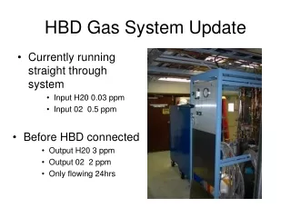
Leak Near Inner Window Putty is not mechanically stable over time. Even slight overpressure inside detector pushes putty out and causes leaks. Will try and glue window from inside when it is open in Instrumentation Clean Room. C.Woody, HBD Working Group Meeting, 8/31/05
Glove Box in HBD Lab C.Woody, HBD Working Group Meeting, 8/31/05
Prototype Readout Board • Problems with first prototype board • Difficulty aligning all layers due to thinness of • board material • Many shorts between signal and ground layer • Test pulse line has high impedance due to thin • copper layer C.Woody, HBD Working Group Meeting, 8/31/05
New Preamp Design • ~ ½ the area of the larger preamp (0.76” x 0.57 “) • Uses small Samtec connector • Uses new op amp with lower bandwidth which is less prone to oscillation C.Woody, HBD Working Group Meeting, 8/31/05
Schedule for New Preamps • Basic design done by Joe Harder • (while home recuperating from surgery !) • Design will be given to layout engineer next week • (will take ~ 1 week to complete) • Will then send out for small prototype run (~ 200 pieces) • (should take ~ 3 weeks) • Test prototypes for oscillation, noise, etc (~ 1 week) • Final design could be sent out within 2 months • Need to design new readout board in parallel C.Woody, HBD Working Group Meeting, 8/31/05
Backup slides from last meeting C.Woody, HBD Working Group Meeting, 8/31/05
Readout Board for Full Scale Prototype • 68 channels laid out to • match FS prototype • Board thickness • 5 FR4 layers ( .004” each ) • 2 Cu layers ( 5 mm each ) • Pulser distributed to • 16/14/24/14 chs for testing • Design layout completed • Waiting for material • Board will be made in • Instrumentation shop • after material arrives B.Yu C.Woody, HBD Working Group Meeting, 8/31/05
Possible Redesign of Preamps • Found new, small header and connector • which could replace presently proposed ones • Present header : 0.57 g Small header : 0.052 g • 10 Cu pins on present PA : 0.13 g connector : 0.087 g • Re-layout to place components on both • sides could reduce board size by ~ factor 2 • one extra layer of FR4 + small amount of Cu, • but possibly go .006” .004” each layer so that • final board thickness stays ~ same • All components stay the same except one • chip which would need to be changed to • prevent possible oscillation ($2.50 x 3000 = $7500) • Could possibly reduce X0 from: • Preamp: 0.95% ~ 0.6% • Header: 0.6% ~ 0.06% • Total: 1.55% 0.66% • (1.46% detector + gas) Samtec Connector & Header Estimate 6 months to redesign and get first pieces back IF Joe Harder were available C.Woody, HBD Working Group Meeting, 8/31/05