Download
1 / 74
1.48k likes | 3.03k Vues
Grounding and Jumpering. Temporary Grounding. Why is it so important? De-energized Circuits become energized accidentally Human Error Contact with energized circuits Induced Voltage Lightning Faults on adjacent circuits. The “A” Approach. Aware--see everything-What if?

E N D
Temporary Grounding Why is it so important? • De-energized Circuits become energized accidentally • Human Error • Contact with energized circuits • Induced Voltage • Lightning • Faults on adjacent circuits
The “A” Approach • Aware--see everything-What if? • Adapt--What is this situation ,no standard approach. What if? • Attack—Don’t violate MY zone, I am responsible for me!
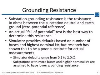
What Conditions Justify Reviewing Grounding & Jumpering Practices • Increased Fault Current Levels • Increased Conductors per Structure • Increased Conductors per Right-of-Way • Age of Protective Grounding Equipment • Accidents Continue to happen
OSHA 29 CFR 1910.269 Guidelines Grounding for the Protection of Employees • Equipotential Zone (EPZ): • “Temporary protective grounds shall be placed at such locations and arranged in such a manner as to prevent each employee from being exposed to hazardous differences in electrical potential.” 1910.269(n)(3) • Question: Is there a difference between: • TRIPPING OR BRACKET GROUNDS • PERSONAL PROTECTION GROUNDING (EPZ)
From page 11-5 of Encyclopedia of Grounding Grounding for the Protection of Employees • PERSONAL PROTECTION GROUNDING – EQUIPOTENTIAL ZONE GROUNDING (EPZ) • A COMBINATION of tripping grounds AND personal grounds installed in a method that BONDS the de-energized cables and equipment with ALL other conductive objects within the work site, limiting the VOLTAGE DIFFERENTIAL (Electrical Potential) exposure to a safe value.
OSHA 29 CFR 1910.269 Guidelines Grounding for the Protection of Employees • Equipotential Zone • Protective Grounding Equipment • Testing • Order of Connection • Order of Removal
OSHA 29 CFR 1910.269 Guidelines Grounding for the Protection of Employees • Equipotential Zone: • “Temporary protective grounds shall be placed at such locations and arranged in such a manner as to prevent each employee from being exposed to hazardous differences in electrical potential.” 1910.269(n)(3)
OSHA 29 CFR 1910.269 Guidelines Grounding for the Protection of Employees • Protective Grounding Equipment: • “Protective grounding equipment shall be capable ofconducting the maximum fault current that could flow at the point of grounding for the time necessary to clear the fault. This equipment shall have an ampacity greater than or equal to that of No. 2 AWG copper. • Protective grounds shall have an impedance low enough to cause immediate operation of protective devices in case of accidental energizing of the lines or equipment.” 1910.269(n)(4)
OSHA 29 CFR 1910.269 Guidelines Grounding for the Protection of Employees • Testing: • “Before any ground is installed, lines and equipment shall be tested and found absent of nominal voltage, unless a previously installed ground is present .” 1910.269(n)(5)
OSHA 29 CFR 1910.269 Guidelines Grounding for the Protection of Employees • Order of Connection: • “When a ground is to be attached to a line or to equipment, the ground-end connection shall be attached first, and then the other end shall be attached by means of a live-line tool.” 1910.269(n)(6)
Order of Connection: “When a ground is to be attached to a line or to equipment, the ground-end connection shall be attached first, and then the other end shall be attached by means of a live-line tool.” 1910.269(n)(6) OSHA 29 CFR 1910.269 Guidelines Grounding for the Protection of Employees IMPORTANT ! - Rubber Gloves are NOT live-line tools
OSHA 29 CFR 1910.269 Guidelines Grounding for the Protection of Employees • Order of Removal: • “When a ground is to be removed, the grounding device shall be removed from the line or equipment using a live-line tool before the ground-end connection is removed. ” 1910.269(n)(7)
Note: All grounding clamps, ferrules and cable meet ASTM F 855 (For the latest information, please reference ASTM F 855 Standard) 1(b). ASTM F 855 DESIGNATION SUMMARY • “Type” – refers to the means of installing a ground clamp (i.e. eyescrew, tee handle, permanent hot stick). • “Grade” - refers to the withstand rating for the ground clamp (e.g. "Grade 5" Clamp is rated at 43 kA for 15 cycles). • “Class” – refers to the clamp jaw surface (i.e. smooth or serrated).
Support Studs • Visually and functionally identifies order of removal
Effects of Current on Man *Short shock values for 165 lbs. person C. F. Dalziel & W. R. Lee, "Lethal Electric Currents“ 1969
Most lightning strikes average 2 to 3 miles long and carry a current of 10,000 Amps at 100 million Volts. • The temperature of a typical lightning bolt is hotter than the surface of the Sun! • A single lightning bolt is roughly the same diameter as a US Quarter or Half Dollar coin . • Lightning can strike as far as 20 miles away from the storm.
History of Electric Power Generation 1820, Separate experiments by Hans Christian Oersted, A.M. Ampere, and D. Arago confirmed the relationship between electricity and magnetism. Experiments lead to the discovery of flowing electric currents. 1826, George Ohm defines the relationship between power, voltage, current and resistance in “Ohms Law.” 1831, Michael Faraday proves that electricity can be induced by changes in an electromagnetic field. 1835, Joseph Henry invents the electrical relay, used to send electrical currents long distances. 1860′s, Mathematical theory of electromagnetic fields published. J.C. Maxwell creates a new era of physics when he unifies magnetism, electricity and light. Maxwell’s four laws of electrodynamics (“Maxwell’s Equations”) eventually lead to electric power, radios, and television. 1878, Thomas Edison forms the Edison Electric Light Company in New York City along with JP Morgan who finances the venture. 1879, After many experiments, Thomas Edison creates an incandescent light bulb that could be used for about 40 hours without burning out. By 1880 his bulbs could be used for 1200 hours. 1880 , JP Morgan is first person to have a private residence electrically wired for the new incandescent light bulb. 1882, Thomas Edison opens the world’s first DC generating station on Pearl Street in New York City.
1883, Nikola Tesla invents the “Tesla coil”, a transformer that changes electricity from low voltage to high voltage making it easier to transport over long distances. The transformer was an important part of Tesla’s alternating current (AC) system, still used to deliver electricity today. 1884, Nikola Tesla arrives in America and starts work with Edison’s Electric Light Company. During this year, Nikola Tesla invents the electric alternator, an electric generator that produces alternating current (AC). 1885, After improving upon Edison’s DC dynamo, Tesla leaves Edison’s company and forms partnership with George Westinghouse after Edison refuses to pay him for his work. 1886, William Stanley develops the induction coil transformer and an alternating current electric system. 1888, Nikola Tesla demonstrated the first “polyphase” alternating current (AC) electrical system. His AC system includes everything needed for electricity production and use such as the electric generator, transformer, transmission system, motors and lights. 1890, War of Currents between Thomas Edison/JP Morgan and Nikola Tesla/George Westinghouse and continues through the 1890’s and early 1900’s. 1892, Anticipating AC to become the dominant form of electric power, JP Morgan gains control of the Edison Electric Light Company and forms General Electric. GE invests heavily into AC power. 1893, The Westinghouse Electric Company used an alternating current (AC) system to light the Chicago World’s Fair. George Westinghouse and Nikola Tesla also win contract to build the first hydro electric power plant at Niagara Falls. Niagara Falls Power Co opens in 1896 and supplies power to Buffalo NY.
Each Phase Connected to a Driven Ground Rod • Problems • Resistance between grounds. • Does not limit voltage drop across the worker. • Different potentials present. • Long cable lengths. • Does not protect against “step” potential.
Rw RJ RJ RJ RE RE RE Equivalent Circuit DiagramEach Phase Connected to a Driven Ground Rod • RJ is the equivalent resistance of the ground leads. • RW is the equivalent resistance of the worker on the structure. • RE is the equivalent resistance of the earth between driven grounds.
Phases Connected to a Common Ground • Improvements • Reduced resistance between phases. • Results in faster system reaction time. • Problems • Ground resistance in parallel with the work area. • Does not limit voltage drop across the worker. • Does not protect against “step” potential
Rw RJ RJ RJ RE Equivalent Circuit DiagramPhases Connected to a Common Ground • RJ is the equivalent resistance of the ground leads. • RW is the equivalent resistance of the worker on the structure. • RE is the equivalent resistance of the earth between driven grounds.
Jumpering from Phase to Phase • Improvements • Reduced number of leads to ground. • Eliminates violent reaction of multiple leads to ground. • Minimum resistance between phases, rapid fault clearing. • Problems • Does not limit voltage drop across the worker • Does not protect against “step” potential • Does not create an equi-potential work zone
Equivalent Circuit DiagramJumpering from Phase to Phase • RJ is the equivalent resistance of the ground leads. • RW is the equivalent resistance of the worker on the structure. • RE is the equivalent resistance of the earth between driven grounds. RJ RJ Rw RJ RE
Equi-Potential Configuration Connect to neutral when available • Improvements • Reduced number of leads to ground. • Eliminates long leads to ground. • Puts conductor, work area, and lineman at the same potential. Creates an Equi-Potential work area. • Problems • Does not protect against “step” potential.
Equivalent Circuit DiagramEqui-Potential Configuration Example • Cable 1/0 AWG Copper, 12’ Long RJ = (12 X .098 mΩ) + .32 mΩ = 1.496 mΩ • RW = 1000 Ω • Fault Current, iF = 12,000 A • Current through the worker by Kirchoff’s Law iW = (RJ)/(RJ+RW) X iF = 18 mA • 1.49/(1.49+1,000)x12,000 =18mA • 100 mA: Fibrillation can occur • 23 mA: Painful & Severe shock RJ RJ Rw RJ
Equivalent Circuit DiagramEqui-Potential Configuration Example • Cable 1/0 AWG Copper, 8’ Long RJ = (8 X .098 mΩ) + .32 mΩ = 1.10 mΩ • RW = 1000 Ω • Fault Current, iF = 12,000 A • Current through the worker by Kirchoff’s Law iW = (RJ)/(RJ+RW) X iF = 13 mA • 1.10/(1.10+1,000)x12,000 =13mA • 100 mA: Fibrillation occurs • Reducing the cable length 4’ reduced the current through the workers body by 26% RJ RJ Rw RJ
HPS Ground Clamp Ratings IEC 61230 / ASTM F855 • IEC 35kA • IEC 40kA • IEC 55kA • ASTM Grade 5 • ASTM Grade 6 • ASTM Grade 5H • ASTM Grade 7H Determination of clamp / ground set depends on available fault current.
Phase Conductor Jumpers Ground Jumper Cluster Bar (chain binder) below working position Neutral Jumper Double Point Grounding • Jumpers connect all three phases together on each side of the work site. • Jumper connects cluster bar to phases on each side of the work site. • Jumper connects cluster bar to system neutral or a ground rod if a neutral is not available. • Provides additional capacity for larger fault currents, (fault current is divided by Ohm’s Law). • If the job requires breaking the circuit at the work site, double-point grounding must be used.
Phase Conductor Jumpers Ground Jumper Cluster Bar (chain binder) below working position Neutral Jumper Single Point Grounding • Jumpers connect all three phases together. • Jumper connects cluster bar to phases. • Jumper connects cluster bar to system neutral or a ground rod if a neutral is not available.
Step & Touch Potential Ground rod test at A.B. Chance Research Center, Centralia, MO
Step Potential (Unprotected) • Dependent upon resistance between “system” ground and workman on the “Earth” ground. • Hazardous voltage potential exists across the workman on the ground. • Solution: Create a zone of Equi-Potential for the workman on the ground. IFAULT RK RF RF R1 R2 R0
Step Potential (Protected) IFAULT R1 RK=resistance across the worker. R0=ground resistance R1=structure resistance R2=ground grid resistance ESTEP=voltage drop across worker IK=current through the worker • The closer the worker is to the structure the greater the potential rise. • Voltage drop across the worker on the ground is limited by the ground grid. • Unprotected workers should stay clear of the work area around the structure ground. RK IFAULT ESTEP R2 IK R0 Potential rise above remote earth during short circuit RK R2 R0 R1
Equi-Mat® Ground Grid • Protection against step potential. • Portable ground grid provides Equi-Potential work zone for groundman. • Limits hazardous voltage drop across the person due to voltage gradient at the ground site. • Meets or exceeds (New) ASTM F2715
Touch Potential (Protected) IFAULT RK=resistance across the worker. R0=ground resistance R1=ground grid resistance ETOUCH=voltage drop across worker IK=current through the worker • The closer the worker is to the structure the greater the potential rise. • Voltage drop across the worker on the ground is limited by the ground grid. • Unprotected workers should stay clear of the work area around the structure ground. R1 ETOUCH RK IFAULT R0 IK Potential rise above remote earth during short circuit RK R1 R0
Tested to ASTM 2715-09 Standard in Hubbell Short Circuit Lab • Results meet or exceeded ASTM Standards for HPS/Chance Equi-Mat. • Test Duration – 14.5 cycles • Ground fault measured at 1132A at 7680V at ground rod. • 3 volts & 3mA measured across man when tested grid up, 4 volts & 4.3mA measured across man when tested grid down. • Mat is designed for grid up use only.
Equi-Mat® Ground Grid • Portable ground grid provides Equi-potential work zone for worker. • Protection against step and touch potential. • Limits hazardous voltage drop across the person due to voltage gradient at the work site. • Now available in Slip Resistant material (Black)
OHSA 1926 Subpart E OHSA §1926.959, Mechanical Equipment (iii) Each employee shall be protected from hazards that might arise from equipment contact with the energized lines. The measures used shall ensure that employees will not be exposed to hazardous differences in potential. Unless the employer can demonstrate that the methods in use protect each employee from the hazards that might arise if the equipment contacts the energized line, the measures used shall include all of the following techniques: • (A) Using the best available ground to minimize the time the lines remain energized, • (B) Bonding equipment together to minimize potential differences, • (C) Providing ground mats to extend areas of Equi-potential, and • (D) Employing insulating protective equipment or barricades to guard against any remaining hazardous potential differences. Meets or Exceeds ASTM F2715
Protection at Truck Worksite • If equipment is grounded, is it safe? • How do we limit a hazardous voltage in the event the equipment becomes energized?
Temporary Grounding EquipmentSelection & Location • Choose ground cable with adequate capacity. • Choose ground clamps with adequate current capacity. • Verify system is de-energized. • Clean connections. • Locate clamps for jumpering. • Minimize cable slack.
Grounding Cable Selection • Size / Fault Current Withstand Capacity. Ratings at 15 and 30 cycles per ASTM F855 • Jacket Color • Yellow, Clear, or Black (Personal preference) • Ferrules • Shrouded or UnShrouded (Depends upon type of stress relief) • Threaded or Smooth (Match to ground clamp terminal) • Copper or Aluminum (Match with the clamp material)
Temporary Grounding Cable • #2, 1/0, 2/0, & 4/0 Copper Cable. • Yellow, Black, & Clear Jacket. • Threaded and Plug Type Compression Ferrules (ASTM F855 recommendation). • Copper Ferrules: Use with bronze body clamps. • Aluminum Ferrules: Use with Aluminum body clamps.