Download

1 / 55
550 likes | 553 Vues
Explore the engineering approach behind finite element analysis through a 2-D example in linear elasticity. Learn about node forces, displacement vectors, stiffness matrices, and virtual displacements.

E N D
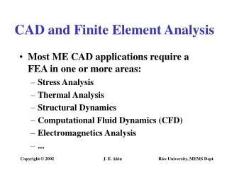
The Engineering Approach Consider a 2-D example in linear elasticity: • A flat plate subjected to forces applied to its edge • The forces are in the plane of the plate • The plate is divided up into triangular elements
The Engineering Approach Consider the element e with nodes i, j and m.
The Engineering Approach • The element communicates with its neighbours by forces • At node i, the force { } has two components, and parallel to the x and y axes. • All six components of force are represented by a vector
The Force Vector • The vector of nodal forces can be expressed in a number of ways where
The Force Vector • The force vector for the complete element is written as,
The Displacement Vector • Each node has two displacement components, u and v (2D analysis) • The displacement of node i parallel to the x-axis is denoted by and that parallel to the y-axis by • The vector of nodal displacements, is where
The Displacement Vector • The complete displacement vector is
The Displacement Vector • If the nodes are displaced by the same vector, the element is translated without strain • This is known as rigid body displacement • If the nodes rotate by the same amount, the element rotates without strain • This is known as a rigid body rotation • The nodal forces are zero for a rigid translation or rotation • The mechanical properties of the material are needed to make the link between nodal displacements and nodal forces
The stiffness matrix • The nodal forces are related to the nodal displacements by the element stiffness matrix, [K]e
The Finite Element Equation • The 6x6 element stiffness matrix is patitioned into nine 2x2 submatrices, so that where the partitions of the stiffness matrix is,
The Finite Element Process • Once the element stiffness matrices are calculated then they are assembled into a global stiffness matrix for the entire model • The externally applied force {F1} produces nodal forces {Fl}, {Fm} and {Fn} acting on the elements l, m and n
The Finite Element Process • For a simple mesh consisting of three elements the global stiffness matrix is found as follows
The Finite Element Process • The element stiffness matrices are; • Element 1 • Element 2 • Element 3
The Finite Element Process • The global stiffness matrix, K, is assembled using the principle of superposition:
The Finite Element Process • In this way, if the vector of external forces applied to the various nodes is [F1 F2 F3 F4 F5 ]T ,then
The Finite Element Process • It is possible to solve for the nodal forces given a complete set of nodal displacements • The more common problem is to solve for the nodal displacements given a set of externally applied forces
The Finite Element Process • The stiffness matrix has a strong leading diagonal • The matrix is square, symmetric and is positive definite • At this point, the assembled stiffness matrix is singular • No solution can be obtained • Physically the model is not fixed in space • All rigid body motions must be restrained before a solution is possible
The Finite Element Process • Adequate restraints have to be inserted • Only one set of nodal displacements is possible for any set of imposed nodal forces. • The nodal displacements are found by solving a set of simultaneous equations • From the displacements the strains are calculated • From the strains the corresponding stresses are found
The Principles of Virtual Displacement Consider a particle acted on by a number of forces, A virtual displacement of the particle is imagined to be so small that the forces applied to the particle remain unchanged in magnitude and direction.
The Principles of Virtual Displacement • In equilibrium the resultant force acting on the particle is zero • The work done by a force is equal to the work done by its components • Forces acting on particle are considered part of net force • The net force is zero (for equilibrium) • The virtual work done by the virtual displacement is zero
The Principles of Virtual Displacement Consider an elastic body represented by a system of two particles joined by an elastic spring • A possible virtual displacement is indicated by the vector ds involving displacement of the particle 2.
The Principles of Virtual Displacement • The force exerted by the spring is equal to the spring constant, k, multiplied by the extension of the spring , Δ • Applying the principle of virtual work
The Principles of Virtual Displacement • The individual contributions have been given in terms of the appropriate scalar product • (kΔ).δs represents the change in the stored energy in the spring • The change in the elastic stored energy caused by the virtual displacement has to be taken into account
The Principles of Virtual Displacement • Consider an elastic solid in equilibrium before and after the imposition of a virtual displacement to a system of forces applied to it.
The Principles of Virtual Displacement • The virtual displacement gives rise to virtual strains • The virtual strains are compatible with the virtual displacements of the forces acting on the solid • The stresses remain unchanged by the virtual displacement • The change in strain energy per unit volume caused by the virtual displacement is
The Principles of Virtual Displacement • The total change in the stored strain energy in the body is • If there are n external forces, each with components in the reference x, y, and z direction, such as • and each undergoes its own virtual displacement
The Principles of Virtual Displacement • The work done by the external forces equals the increase in the stored energy, by the Principle of Virtual Work, • The left-hand side of this equation can be replaced by an integral over an area in the case of distributed loads • The Principle of Virtual Displacements is used to find nodal forces in formulated element stiffness matrices
The Theory of Minimum Total Potential Energy It was found using the Principle of Virtual Work that • The left-hand side of this equation is the work done by the external forces as a result of the set of virtual displacements • This is the loss in the potential energy of the system of external forces • The right-hand side is the increase in the strain energy of the elastic body
The Theory of Minimum Total Potential Energy If, is the potential energy of the system, then • In the equilibrium condition the potential energy of the system has an extreme value of a maximum or a minimum.
Shape Function • The displacement of any point within an element is a function of the nodal displacements and of the position of the point. This is expressed by means of shape functions.
Shape Function • For any point P with coordinates (x, y) the displacement can be expressed as where and • Each shape function is a function of position, Ni=Ni (x,y)
Conditions the shape functions must fulfil • At node i, the displacement is given in terms of the nodal displacements • For this to be true for any value of nodal displacement, it can be seen that Ni must equal 1 and the shape functions at all other nodes zero. The same is true for all the other shape functions, i.e.
Conditions the shape functions must fulfil • The displacement must be continuous between elements • The shape function of a node is zero along a boundary not containing that node. • The shape functions should be able to represent rigid translation, i.e. • This condition requires that Ni + Nj + Nm=1 for all points in the element
Conditions the shape functions must fulfil • The shape functions must be able to represent rigid rotation
Conditions the shape functions must fulfil • A point P, with coordinates (x, y) is subjected to a small rotation about the origin, causing it to move through a distance rө. The component of the displacement in the x direction, u, is given by and since This can be written as;
Conditions the shape functions must fulfil • Similarly for the nodal displacement By substituting these values into the nodal displacement equation, hence Similarly
Conditions the shape functions must fulfil • For triangular elements, suitable shape functions can be found from the area and sub-areas of the triangle, these are known as area shape functions
Strain-Displacement Relationship • The strains at any point in a 2-D state of strain are given by • In matrix form
Strain-Displacement Relationship • For a three node triangular element the strain-displacement relationship can be expressed as,
Strain-Displacement Relationship • The strain-displacement relationship is generally expressed in matrix form as, where [B] is called the strain matrix • Similarly the virtual displacements and strains are related by,
Strain-Displacement Relationship • The strains are related to the stresses by Hooke’s law. The elasticity matrix [D] for plane stress is, where E is Young’s modulus of elasticity and nis Poisson ratio • The [D] matrix is always symmetrical even when the material exhibits anisotropic (but linear) elasticity.
Strain-Displacement Relationship • The stress can be expressed in terms of the displacement by combining the strain-displacement and stress-strain relationships; • The stresses and strains throughout the element can be calculated from the nodal displacements.
Use of the principle of virtual displacements Imagine a set of virtual nodal displacements is applied to the element. Since it is considered that the deformation of the element is caused by the nodal forces, we equate the virtual work done by these forces when the nodes undergo their virtual displacements to increase the elastic potential energy of the element. • {e*} is the virtual strains caused by the virtual nodal displacements {d*}e
Use of the principle of virtual displacements • In general {e*} will be a function of position within the element, although in this case, stress and strain are constant over the element. • The stress-displacement relationship is; • The virtual strain-displacement relationship is;
Use of the principle of virtual displacements • Thus • The nodal displacements are not functions of position; • Since this is true for any arbitrary set of we have
Use of the principle of virtual displacements • This is the finite element equation for the element • From the definition of the element stiffness matrix, • by comparing previous equations we have the stiffness matrix
Use of the principle of virtual displacements • u and v are linear functions of x and y • The strains and stresses are therefore constant • [B]T[D][B] is thus constant • The components of [K]e are therefore the components of [B]T[D][B] multiplied by the volume of the element • In other higher order elements this is not strictly true and numerical methods of integration are frequently used • [K]e must be symmetrical ([K]eT=[K]e)
The Use of the Principle of Minimum Potential Energy • The elastic energy stored per unit volume of a deformed body is • In the system consisting of the triangular element and the nodal forces, taking the zero of potential energy to be when the points of application of the nodal forces are at the respective nodes in the un-deformed element. Then the potential energy of the system is,
The Use of the Principle of Minimum Potential Energy • The potential energy can be written as, • and are constant over the element and can be taken outside the integral