Download
1 / 24
250 likes | 423 Vues
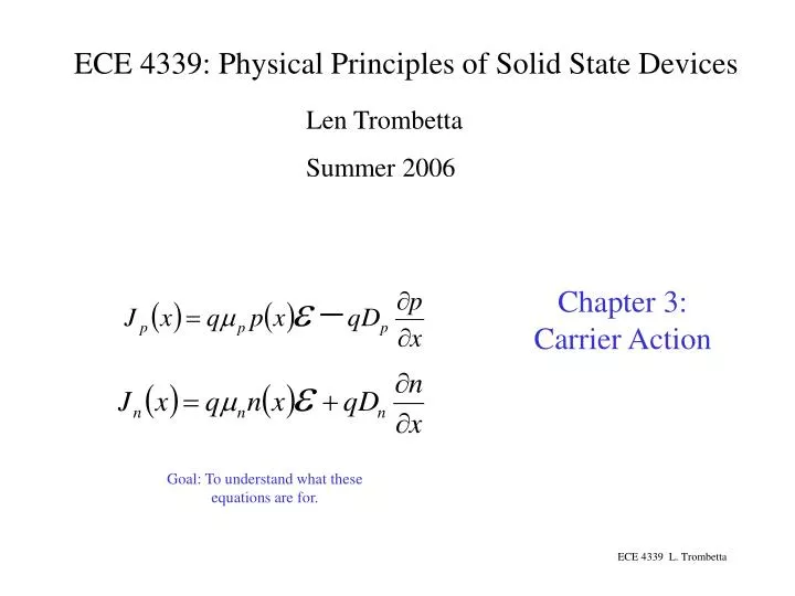
ECE 4339: Physical Principles of Solid State Devices. Len Trombetta Summer 2006. Chapter 3: Carrier Action. Goal: To understand what these equations are for.

E N D
ECE 4339: Physical Principles of Solid State Devices Len Trombetta Summer 2006 Chapter 3: Carrier Action Goal: To understand what these equations are for. ECE 4339 L. Trombetta
Initially the mobility of electrons and holes increases linearly with electric field, but then tapers off and saturates at high fields. Often, modern devices operate at the saturated velocity. ECE 4339 L. Trombetta
We will be reading from this chart (and the one on the next page) a lot. ECE 4339 L. Trombetta
A B EC DE EV + - DV = VB - VA Relationship between energy and potential for an electron energy band diagram. DE = -qDV increasing electron energy increasing electron potential The electron moves to the left (down the hill and toward lower energy) under the action of the potential. Note that the right-hand side of the figure is at a more negative potential and has a higher energy than the left-hand side. This is simple electrostatics: the electron has higher energy toward the right because like-charges repel: the electron doesn’t want to be in a “negative” region. ECE 4339 L. Trombetta
V = -E/q e = - dV/dx ECE 4339 L. Trombetta
Fig. 3.10 (previous slide) provides more detail on the relationships between energy, voltage, and electric field as they relate to the energy band diagram. Note that the vertical axis gives total electron energy, which is the sum of kinetic and potential energy. The relevant equations for an electron are… potential energy We have defined a reference that is completely arbitrary. We can put Eref anywhere because we will always deal only with differences in potential and energy. That’s why we don’t have to put values on our vertical axis: it doesn’t matter where E = 0 happens to be. kinetic energy Kinetic energy is the difference between the total energy E - Eref and the potential energy. electric field Electric field is the negative of the gradient of the potential (E&M). The reference energy Eref is constant, so the gradient of Eref is 0. Also, EC, EV and Ei all “track” one another so it makes no difference which one we use for the gradient. ECE 4339 L. Trombetta
If ND is a function of distance (i.e., not constant), and if no current is flowing, then… …we will get an electric field from the non-uniform carrier density. ECE 4339 L. Trombetta
Some definitions… Generation: the production of electron hole pairs Recombination: the removal of electron hole pairs Equilibrium: a condition in which the energy of the system is determined only by the temperature. (For semiconductors this means there is no current flowing or light shining anywhere.) Steady State: a condition in which the every process (recombination, for example) is balanced by an inverse process (generation). A system in steady state is not necessarily in equilibrium. ECE 4339 L. Trombetta
Recombination/Generation processes Here we look at the ways in which electrons and holes can be generated or recombine. This will be important in understanding how current flows or how semiconductors respond to light. ECE 4339 L. Trombetta
Bottom Line: If a semiconductor is not in equilibrium (which will happen if current is flowing or the semiconductor is exposed to light), R/G processes will come in to play to try to return the system to equilibrium. ECE 4339 L. Trombetta
In Figure 3.15 b and e, ET is the energy of a “trap”; the situation is similar to a donor or acceptor, except that the energy level is far from the band edges (whereas donor/acceptor levels are close to the band edges). This figure shows some of the elements that generate traps in Si, and indicates their energy levels relative to the band edges. ECE 4339 L. Trombetta
Eg Eg eV Recall our formula for the energy of a “free” QM particle of wavenumber k: mn* = 0.25 Here is the formula applied to electrons and holes, assumed to be free, in a semiconductor. mp* = 0.10 m-1 But electrons and holes aren’t quite free in semiconductors. Here is a more accurate picture for two cases: “direct” and “indirect” semiconductors. ECE 4339 L. Trombetta
Electron/hole recombination here results in light output. Electron/hole recombination here results in heat output. ECE 4339 L. Trombetta
EC EC EV EV More complete picture of absorption/transmission Simple picture of absorption/transmission a large: material is opaque hn > EG x a small: material is transparent hn < EG x ECE 4339 L. Trombetta
Large input impedance Idea: RS (semiconductor resistance) is large unless light is shining on it, in which case it is small. In the dark, vL will be small, but during a light flash, it will rise (see “scope” trace). As excess carriers recombine, RS goes back up, with a time constant given by the minority carrier lifetime. ECE 4339 L. Trombetta
GL is the rate at which excess carriers are being generated (cm-3s-1). This equation says that when we shine a light on the sample beginning at t = 0, the excess carriers buildup at a rate determined by the minority carrier lifetime tp. After the light has been on for a long time (several time constants), the total excess hole density is GLtp. ECE 4339 L. Trombetta
If we “flash” the light, we can get watch minority carriers decay exponentially, again with a time constant given by the minority carrier lifetime. In this figure we imagine flashing the light repeatedly. ECE 4339 L. Trombetta
Here the illumination is constant, but it hits only at the end of the sample. We are now looking at how the excess carrier concentration decays into the bulk of the sample. This happens because carriers diffuse and recombine at the same time. ECE 4339 L. Trombetta