Download
1 / 10
100 likes | 203 Vues
PALM-3000 Instrument Architecture. Antonin Bouchez PALM-3000 Requirements Review November 12, 2007. Instrument Concept. Instrument Requirements Document: http://www.oir.caltech.edu/twiki_oir/bin/view.cgi/Palomar/Palm3000/SystemsEngineering. PALMAO components to be reused:

E N D
PALM-3000 Instrument Architecture Antonin Bouchez PALM-3000 Requirements Review November 12, 2007
Instrument Concept Instrument Requirements Document: http://www.oir.caltech.edu/twiki_oir/bin/view.cgi/Palomar/Palm3000/SystemsEngineering PALMAO components to be reused: • AO cart (used to transport the AO system) • AO spit (used to support the AO system during lab work) • AO optical bench and Cassegrain interface support structure. • Relay optics: eg. Off-axis parabolas (OAP), fast steering mirror (FSM), fold mirrors. • 349-actuator Xinetics deformable mirror (DM349). • Low-Order Wavefront Sensor (LOWFS), as an interim tip/tilt/focus sensor. Project phases: • Phase 0: Interim relay (current optics recoated, focus shifted). • Phase 1: Develop and deploy DM3368, HOWFS, wavefront processor, etc. • Phase 2: Develop and deploy IRTT, TWFS and related electronics and software.
OAP1 FSM OAP2 DM349 FM1 FM3 DM3368 FM2 Optical Layout (1) AO Stimulus: • Simultaneous NGS and LGS stimuli. • X-Y translation of NGS stimulus to accommodate multiple instruments. AO Relay: • A single off-axis parabola relay. • DM3368 at the pupil • DM3349 conjugate to <±1.5 km. 3
Optical Layout (2) • Wavefront sensor beam splitting • Large beamsplitters (6-8”) are fixed, only changed out with instruments. • Splitter #3 on actuated stage to switch between NGS and LGS modes. • Space constraints pose greatest chanllenge. 4
Science Instrument #1 IRTT #2 #3 TWFS HOWFS ACQ Beam Splitter Layout Schematic
Wavefront Sensors High Order WFS (Phase 1) • NGS and LGS sensor, using CCD50 detector (128x128) • 8x8, 16x16, 32x32, 64x64 pupil sampling. • Adjustable field stop for spatial filtering. Infrared Tip/Tilt WFS (Phase 2) • Wide-field imaging camera based on HAWAII2-RG. • Full-field acquisition and region-of-interest readout. • Single filter, J+H (1100-1780nm). Low-Order WFS (Phase 1) • 3x3 Shack-Hartmann sensor using CCD39. Truth WFS (Phase 2) • 2x2 Shack-Hartmann sensor using CCD39 • Provides focus and back-up tip/tilt capability. 6
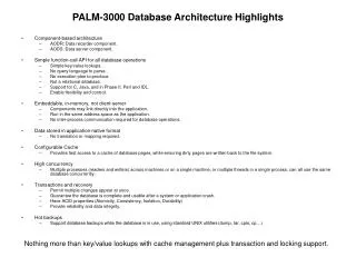
DM I/F CAM I/F CAM I/F GPU 2 GPU 1 LWFP SWT I/F SWT I/F CPU CPU D/A PC 0 PC 1 … … PC 8 Switched Network Ether-Net I/F Burst Data RAM Disk Array Data User 1 SWT I/F Data Server … CPU … Data User n Gigabit Ethernet Electronics Cassegrain Cage • Controller rack • DM349 driver rack • DM3368 driver rack. • Active cooling! Computer room • Wavefront Processor: NVIDIA 8800 GPUs (17) Housed in 9 PCs • Telemetry server Data room • Operator workstation 7
DM control algorithms Solution: Implement both pathways for DM349 control. 8
Operational Systems Software • Provide low-level control of all AO system functions (servo loop state, motor positions, etc.) • Provide displays of system status and performance (live display of servo loop state, WFS pixels, DM actuator positions, servo loop strip charts). • High-level automations: • Guide star acquisition on all wavefront sensors • Wavefront sensor background recording • Wavefront sensor to DM registration • Flexure and atmospheric refraction compensation • Phase-diversity measurement of the static aberrations seen by the science instrument • Optimization of the LGS reconstructor using Palomar MASS Cn2 data 9
Laser Guidestar Facility Planned Improvements • Relocate the Chicago Sum Frequency Laser to the lower Coude lab. • Potentially space of a second laser in the same lab. • Improvements to LLT image quality are still required. • Aircraft safety system automation based on Table Mountain Observatory system. Lower Coude 10