Download
1 / 27
290 likes | 494 Vues
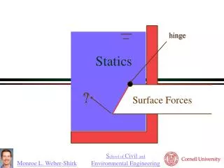
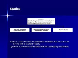
Statics in Bridges. What is a force?. A force is a push or pull on an object (compression and tension). Stationary objects are static. No net forces No net moments (torques). Are there forces on you now?. Gravity is pulling you down. The stool is pushing you up. Force is compression.

E N D
What is a force? • A force is a push or pull on an object (compression and tension).
Stationary objects are static. • No net forces • No net moments (torques)
Are there forces on you now? • Gravity is pulling you down. • The stool is pushing you up. • Force is compression. • Each leg supports ¼ of the weight • Total forces are zero (statics).
What forces are on this girl? • Net force is zero. • Gravity pulls the girl down (weight). • Force in the line is tension. • Sample calculation-
Bending is Bad • Bending- Beams have very little bending strength. • Never design a structure that relies on bending strength to support a load.
Design and construction ideas: 1) Triangles are a construction engineer’s best friend, i.e. there are no bending moments in triangular elements. Good design Bad design (truss strength depends on bending strengths of members)
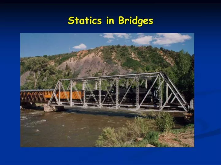
Truss Bridges • Your bridge will be essentially a truss.
In a truss bridge forces are at an angle. Since the bridge is stationary the Net force must be zero.
Beams and loads--compression: d L Beam in compression Failure occurs two ways: 1) When L/d < 10, failure is by crushing 2) When L/d > 10, failure is by buckling We are almost always concerned with failure by buckling.
Compression- Buckling Strength: F = (k)d4/L2 If a beam of length L and diameter d can support a compressive load of F, d F L then a beam of length L/2 and diameter d can support a compressive load of 4F. d 4F L/2
Compression- Buckling Strength: F = (k)d4/L2 d F L and a beam of length L and diameter 2d can support a compressive load of 16F. 2d 16F L
Compression- Buckling Strength: F = (k)d4/L2 • In compression short and fat members are good. • Bigger beams can be fabricated out of smaller beams, as in a truss. The fabricated beam will have the same buckling strength as a solid beam, provided the buckling/tension strengths of the component beams are not exceeded.
Tension: F=kR2 Beam under tension • Failure occurs when tensile strength is exceeded. • Maximum load is tensile strength times cross-sectional area. • Load capacity does not depend on length.
Use Bridge Designer to calculate loads: http://www.jhu.edu/~virtlab/bridge/bridge.htm Tension members are in RED Compression members are in BLUE
Design and construction ideas: • Taller is better: note loads on these two structures.
Which is the better design and why (cont.)? a) b) a) b)
Calculate Tension & Compression Values for the Balsa Bridge • Tension: F=kR2 Balsa wood k=19.9 MPa • Compression: F= Eπ3R4 64L2 Balsa wood E=1130 MPa • E= young’s modulus (a measure of the rigidity of a material, the large E is the less the material will deform when under stress)
Some properties of balsa wood (dry) For comparison, cast aluminum (wet or dry): 1. Ultimate tensile strength ~10,000psi 2. Stiffness E~10,000,000psi
Design and construction ideas: • Don’t forget about the 3rd dimension. A good design in the x-y plane, may be a terrible one in the z-direction. • Plan the total bridge design. Estimate the weight of each of the components, so that you will not exceed the weight limit (95 grams). • Make a full-size pattern of your bridge. Build the bridge on this pattern. This will ensure that all components will assemble properly (use wax paper). • Rough cut members then sand to the desired length. • Common disqualifications: • angles must be over 30 degrees. • Gluing cannot go beyond 3mm from a joint. • Mass of bridge <95 grams
Types of Trusses K Truss Warren/ Neville Truss Pratt Truss Howe Truss
Use Bridge Builder • Go to http://www.jhu.edu/~virtlab/virtual-laboratory/