Download
1 / 14
140 likes | 225 Vues
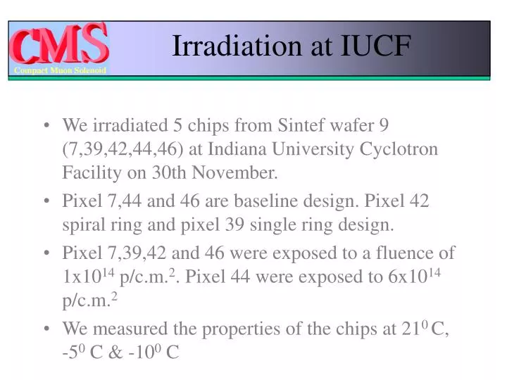
Irradiation at IUCF. We irradiated 5 chips from Sintef wafer 9 (7,39,42,44,46) at Indiana University Cyclotron Facility on 30th November. Pixel 7,44 and 46 are baseline design. Pixel 42 spiral ring and pixel 39 single ring design.

E N D
Irradiation at IUCF • We irradiated 5 chips from Sintef wafer 9 (7,39,42,44,46) at Indiana University Cyclotron Facility on 30th November. • Pixel 7,44 and 46 are baseline design. Pixel 42 spiral ring and pixel 39 single ring design. • Pixel 7,39,42 and 46 were exposed to a fluence of 1x10¹⁴ p/c.m.2. Pixel 44 were exposed to 6x10¹⁴ p/c.m.2 • We measured the properties of the chips at 210 C, -50 C & -100 C
Measurement Technique Bulk Material Wire bond (1st GR) Wire bond N+ Diode Guard Rings N+ ring P+ Cu tape Cu tape Conducting rubber sheet Ammeter Hi Wire Pixels are bumped but not bonded with anything. The whole structure was kept inside the refrigerator and the wire came out of the refrigerator.
What we expected • Increase incurrent I=.V.eq (This equation gives the change of current in the plateau region of the IV curve. For these pixels the plateau region is between 50V to 250V) • = 4.0x10⁻¹⁷ A/cm1 , V = 0.007478 cm3 eq = 1(6)x1014 cm-2 • I = 3.0x10⁻⁵ (17.9x10⁻⁵) A • A single pixel - 0.015x0.015 cm2 • Increase in current through a single pixel • Isingle pixel = I x 0.015x0.015/(0.2493) A = 27.0 (162) nA • 1Value of from Rose Collaboration - http://www.physics.purdue.edu/vertex/talks/feick.pdf
What we got • For Pixel 7 I200V = 2.67x10⁻⁵ A I300V = 6.94x10⁻⁵ A • For Pixel 39 I200V = 3.11x10⁻⁵ A I300V = 4.98x10⁻⁵ A • For Pixel 42 I200V = 2.80x10⁻⁵ A I300V = 5.69x10⁻⁵ A • For Pixel 46 I200V = 2.85x10⁻⁵ A I300V = 3.90x10⁻⁵ A] • For Pixel 44 I200V = 1.16x10⁻⁴ A I300V = 2.77x10⁻⁴ A • Pixel 44 received 6 times higher fluence than the other pixels. Leakage current of pixel 44 is 4(5) times higher than the other pixels at 200(300)V.
Pixel 46 Fluence -1x10¹⁴ Design A
Extra Current Current compliance was 1mA This indicates that the current is coming from diode (pixels).
Pixel 7 - Depletion Voltage Fluence -1x10¹⁴ Leakage current at depletion voltage is 0.71A (1.1nA/pixel) Design A Full Depletion at 33 V
Summary • We have to understand the rise of current at the kink between 200 to 300V. • We plan to do the measurement at -20 • We plan to bump bond this pixel arrays to ROC and to measure them with source.
Is it possible to measure the potential of a central pixel when the guard region is biased ? Silver Epoxy Pixel • First the measurement was done without grounding the epoxy. • Next the measurement was done with the epoxy grounded. • Measurement was done with one probe at the center pixel, one probe at the silver epoxy and a wire bond connection with the diode. This measurement was done on SINTEF wafer 24 Pixel 46 before irradiation. We haven’t done the measurement after irradiation.
Connection Setup for measuring the voltage at a center Pixel V Bulk Material N+ Probe Probe P+ N+ ring Wire bond Diode Guard Rings Hi
Connection Setup for measuring the Interpixel Capacitance Bulk Material ~ C N+ Probe Probe P+ N+ ring Wire bond Diode Guard Rings Hi