Download
1 / 40
480 likes | 722 Vues
VLANs (Virtual LANs). CIS 83 Fall 2006 CCNA 3 Rick Graziani Cabrillo College. VLAN introduction. VLANs provide segmentation based on broadcast domains. VLAN = Subnet VLANs can logically segment switched networks based on: Physical location (Example: Building)

E N D
VLANs (Virtual LANs) CIS 83 Fall 2006 CCNA 3 Rick Graziani Cabrillo College
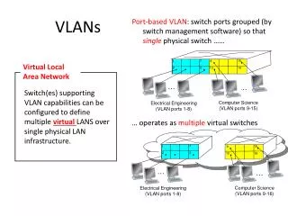
VLAN introduction • VLANs provide segmentation based on broadcast domains. • VLAN = Subnet • VLANs can logically segment switched networks based on: • Physical location (Example: Building) • Organization (Example: Marketing) • Function (Example: Staff) vlan 10 Default vlan 1 Default vlan 1 Courtesy of Rick Graziani graziani@cabrillo.edu
VLAN introduction One link per VLAN or a single VLAN Trunk (later) • VLANs are created to provide segmentation services traditionally provided by physical routers in LAN configurations. • VLANs address scalability, security, and network management. Without VLANs 10.1.0.0/16 10.1.0.0/16 With VLANs 10.2.0.0/16 10.2.0.0/16 10.3.0.0/16 10.3.0.0/16 Courtesy of Rick Graziani graziani@cabrillo.edu
Two Subnets, One Switch, No VLANs • Layer 2 Broadcasts • What happens when 10.1.0.10 sends an ARP Request for 10.1.0.30? 10.1.0.10/16 DG: 10.1.0.1 10.2.0.20/16 DG: 10.2.0.1 10.1.0.30/16 DG: 10.1.0.1 10.2.0.40/16 DG: 10.2.0.1 Courtesy of Rick Graziani graziani@cabrillo.edu
Two Subnets, One Switch, No VLANs • Layer 2 Broadcasts • Switch floods it out all ports. • All hosts receive broadcast, even those on a different subnet. • Layer 2 broadcast should be isolated to only that network. • Note: If the switch supports VLANs, by default all ports belong to the same VLAN and it floods it out all ports that belong to the same VLAN as the incoming port (coming). 10.1.0.10/16 DG: 10.1.0.1 10.2.0.20/16 DG: 10.2.0.1 10.1.0.30/16 DG: 10.1.0.1 10.2.0.40/16 DG: 10.2.0.1 Courtesy of Rick Graziani graziani@cabrillo.edu
Two Subnets, One Switch, No VLANs • Layer 2 Unknown Unicasts • This is the same for unknown unicasts. 10.1.0.10/16 DG: 10.1.0.1 10.2.0.20/16 DG: 10.2.0.1 10.1.0.30/16 DG: 10.1.0.1 10.2.0.40/16 DG: 10.2.0.1 Courtesy of Rick Graziani graziani@cabrillo.edu
Two Subnets, One Switch, No VLANs • Even though hosts are connected to the same switch (or even hub), devices on different subnets must communicate via a router. • Remember a switch is a layer 2 device, it forwards by examining Destination MAC addresses, not IP addresses. Fa 0/0 Fa 0/1 10.1.0.1/16 10.2.0.1/16 10.1.0.10/16 DG: 10.1.0.1 10.2.0.20/16 DG: 10.2.0.1 10.1.0.30/16 DG: 10.1.0.1 10.2.0.40/16 DG: 10.2.0.1 Courtesy of Rick Graziani graziani@cabrillo.edu
Traditional Solution: Multiple Switches • The traditional solution is have devices on the same subnet connected to the same switch. • This provides broadcast and unknown unicast segmentation, but is also less scalable. Fa 0/0 Fa 0/1 10.1.0.1/16 10.2.0.1/16 ARP Request 10.1.0.10/16 DG: 10.1.0.1 10.1.0.30/16 DG: 10.1.0.1 10.2.0.20/16 DG: 10.2.0.1 10.2.0.40/16 DG: 10.2.0.1 Courtesy of Rick Graziani graziani@cabrillo.edu
Broadcast domains with VLANs and routers Port 1 VLAN 10 Port 4 VLAN 20 Port 9 VLAN 10 Port 12 VLAN 20 • A VLAN is a broadcast domain created by one or more switches. • VLANs are assigned on the switch and correspond with the host IP address. • Each switch port can be assigned to a different VLAN. 10.1.0.10/16 DG: 10.1.0.1 10.2.0.20/16 DG: 10.2.0.1 10.1.0.30/16 DG: 10.1.0.1 10.2.0.40/16 DG: 10.2.0.1 Courtesy of Rick Graziani graziani@cabrillo.edu
Broadcast domains with VLANs and routers Port 1 VLAN 10 Port 4 VLAN 20 Port 9 VLAN 10 Port 12 VLAN 20 • Ports assigned to the same VLAN share the same broadcast domain. • Ports in different VLANs do not share the same broadcast domain. ARP Request 10.1.0.10/16 DG: 10.1.0.1 10.2.0.20/16 DG: 10.2.0.1 10.1.0.30/16 DG: 10.1.0.1 10.2.0.40/16 DG: 10.2.0.1 Courtesy of Rick Graziani graziani@cabrillo.edu
VLAN operation Courtesy of Rick Graziani graziani@cabrillo.edu
Static VLANS • Static membership VLANs are called port-based and port-centric membership VLANs. • This is the most common method of assigning ports to VLANs. • As a device enters the network, it automatically assumes the VLAN membership of the port to which it is attached. • There is a default VLAN, on Cisco switches that is VLAN 1. Default VLAN 1 Default VLAN 1 VLAN 10 Configured Switch(config)#interface fastethernet 0/9 Switch(config-if)#switchport access vlan 10 Courtesy of Rick Graziani graziani@cabrillo.edu
VLAN operation Port 1 VLAN 10 Port 4 VLAN 20 Port 9 VLAN 10 Port 12 VLAN 20 • VLANs are assigned on the switch port. • In order for a host to be a part of that VLAN, it must be assigned an IP address that belongs to the proper subnet. • Remember: VLAN = Subnet 10.1.0.10/16 DG: 10.1.0.1 10.2.0.20/16 DG: 10.2.0.1 10.1.0.30/16 DG: 10.1.0.1 10.2.0.40/16 DG: 10.2.0.1 Courtesy of Rick Graziani graziani@cabrillo.edu
VLAN operation • Dynamic membership VLANs are created through network management software. (Not as common as static VLANs) • CiscoWorks 2000 or CiscoWorks for Switched Internetworks is used to create Dynamic VLANs. • Dynamic VLANs allow for membership based on the MAC address of the device connected to the switch port. • As a device enters the network, it queries a database within the switch for a VLAN membership. Courtesy of Rick Graziani graziani@cabrillo.edu
. Two Types of VLANs • End-to-End or Campus-wide VLANs • Geographic or Local VLANs Courtesy of Rick Graziani graziani@cabrillo.edu
End-to-End or Campus-wide VLANs This model is no longer recommended by Cisco and other vendors, unless there is a specific need for this method. Courtesy of Rick Graziani graziani@cabrillo.edu
Geographic or Local VLANs This model is the recommended method. More in CIS 187 (CCNP 3). Courtesy of Rick Graziani graziani@cabrillo.edu
80/20 and 20/80 Rule • The network is engineered, based on traffic flow patterns, to have 80 percent of the traffic contained within a VLAN. • The remaining 20 percent crosses the router to the enterprise servers and to the Internet and WAN. • This is known as the 80/20 rule. • Note: • With today’s traffic patterns, this rule is becoming obsolete. • The 20/80 rule applies to many of today’s networks, with 20% of the traffic within a VLAN, and 80% outside the VLAN. Courtesy of Rick Graziani graziani@cabrillo.edu
Geographic or Local VLANs • As many corporate networks have moved to centralize their resources, end-to-end VLANs have become more difficult to maintain. • Users are required to use many different resources, many of which are no longer in their VLAN. • Because of this shift in placement and usage of resources, VLANs are now more frequently being created around geographic boundaries rather than commonality boundaries. Courtesy of Rick Graziani graziani@cabrillo.edu
Quick Introduction to Trunking • More in the next presentation. Courtesy of Rick Graziani graziani@cabrillo.edu
VLAN Trunking/Tagging • VLAN Tagging is used when a link needs to carry traffic for more than one VLAN. • Trunk link: As packets are received by the switch from any attached end-station device, a unique packet identifier is added within each header. • This header information designates the VLAN membership of each packet. Courtesy of Rick Graziani graziani@cabrillo.edu
VLAN Trunking/Tagging • The packet is then forwarded to the appropriate switches or routers based on the VLAN identifier and MAC address. • Upon reaching the destination node (Switch) the VLAN ID is removed from the packet by the adjacent switch and forwarded to the attached device. • Packet tagging provides a mechanism for controlling the flow of broadcasts and applications while not interfering with the network and applications. • This is known as a trunk link or VLAN trunking. Courtesy of Rick Graziani graziani@cabrillo.edu
VLAN Trunking/Tagging • VLAN Tagging is used when a single link needs to carry traffic for more than one VLAN. No VLAN Tagging VLAN Tagging Courtesy of Rick Graziani graziani@cabrillo.edu
VLAN Trunking/Tagging • There are two major methods of frame tagging, Cisco proprietary Inter-Switch Link (ISL) and IEEE 802.1Q. • ISL used to be the most common, but is now being replaced by 802.1Q frame tagging. • Cisco recommends using 802.1Q. • VLAN Tagging and Trunking will be discussed in the next chapter. Courtesy of Rick Graziani graziani@cabrillo.edu
Configuring VLANs vlan 10 Default vlan 1 Default vlan 1 Courtesy of Rick Graziani graziani@cabrillo.edu
Configuring static VLANs • The following guidelines must be followed when configuring VLANs on Cisco 29xx switches: • The maximum number of VLANs is switch dependent. • 29xx switches commonly allow 4,095 VLANs • VLAN 1 is one of the factory-default VLANs. • VLAN 1 is the default Ethernet VLAN. • Cisco Discovery Protocol (CDP) and VLAN Trunking Protocol (VTP) advertisements are sent on VLAN 1. (later) • The Catalyst 29xx IP address is in the VLAN 1 broadcast domain by default. Courtesy of Rick Graziani graziani@cabrillo.edu
. Creating VLANs • Assigning access ports (non-trunk ports) to a specific VLAN Switch(config)#interface fastethernet 0/9 Switch(config-if)#switchport access vlan vlan_number Switch(config-if)#switchport mode access • Create the VLAN: (This step is not required and will be discussed later.) Switch#vlan database Switch(vlan)#vlan vlan_number Switch(vlan)#exit Courtesy of Rick Graziani graziani@cabrillo.edu
. Creating VLANs • Assign ports to the VLAN Switch(config)#interface fastethernet 0/9 Switch(config-if)#switchport access vlan 10 Switch(config-if)#switchport mode access • access – Denotes this port as an access port and not a trunk link (later) vlan 10 Default vlan 1 Default vlan 1 Courtesy of Rick Graziani graziani@cabrillo.edu
Creating VLANs vlan 300 Default vlan 1 Default vlan 1 Switch(config)#interface fastethernet 0/9 Switch(config-if)#switchport access vlan 300 Switch(config-if)#switchport mode access Courtesy of Rick Graziani graziani@cabrillo.edu
Configuring Ranges of VLANs Switch(config)#interface fastethernet 0/5 Switch(config-if)#switchport access vlan 2 Switch(config-if)#switchport mode access Switch(config-if)#exit Switch(config)#interface fastethernet 0/6 Switch(config-if)#switchport access vlan 2 Switch(config-if)#switchport mode access Switch(config-if)#exit Switch(config)#interface fastethernet 0/7 Switch(config-if)#switchport access vlan 2 Switch(config-if)#switchport mode access vlan 2 Courtesy of Rick Graziani graziani@cabrillo.edu
. Configuring Ranges of VLANs • This command does not work on all 2900 switches, such as the 2900 Series XL. • This format of this command may vary somewhat on various 2900 switches. • It does work on the 2950. vlan 3 Switch(config)#interface range fastethernet 0/8 - 12 Switch(config-if)#switchport access vlan 3 Switch(config-if)#switchport mode access Switch(config-if)#exit Courtesy of Rick Graziani graziani@cabrillo.edu
. Creating VLANs SydneySwitch(config)#interface fastethernet 0/1 SydneySwitch(config-if)#switchport mode access SydneySwitch(config-if)#exit Note: The switchport mode accesscommand should be configured on all ports that the network administrator does not want to become a trunk port. • This will be discussed in more in the next chapter, section on DTP. vlan 300 Default vlan 1 Default vlan 1 Courtesy of Rick Graziani graziani@cabrillo.edu
Creating VLANs • By default, all ports are configured as switchport mode dynamic desirable, which means that if the port is connected to another switch with an port configured with the same default mode (or desirable or auto), this link will become a trunking link. (See my article on DTP on my web site for more information.) • Both the switchport access vlancommand and theswitchport mode accesscommand are recommended. (later) • This will be discussed in more in the next chapter, section on DTP. This link will become a trunking link unless one of the ports is configured with as an access link, I.e. switchport mode access Default: dynamic desirable Courtesy of Rick Graziani graziani@cabrillo.edu
Verifying VLANs – show vlan vlan 1 default vlan 2 vlan 3 Courtesy of Rick Graziani graziani@cabrillo.edu
Verifying VLANs – show vlan brief vlan 1 default vlan 2 vlan 3 Courtesy of Rick Graziani graziani@cabrillo.edu
Deleting VLANs Switch(config-if)#noswitchport access vlan vlan_number • This command will reset the interface to VLAN 1. • VLAN 1 cannot be removed from the switch. Courtesy of Rick Graziani graziani@cabrillo.edu
Accessing/Managing the Switch The IP Address, Subnet Mask, and Default Gateway on a switch is for the same purposes as when you configure it for a host. Note: The switch must be configured with a vty login/password and a privileged password for telnet access. IP Address and Subnet Mask • By default, VLAN 1 is the “management VLAN”. • This is where you assign the IP Address and Subnet Mask to the switch. • This address is for management purposes only and does not affect the Layer 2 switching operations of the switch. • The address allows you the ability to ping the switch or telnet into the switch. Default Gateway • The default gateway is also used for management purposes. • Once you are telnetted into the switch, if you need to ping or telnet into a device on another network, the default-gateway is where those frames will be sent. Switch(config)#interface vlan 1 Switch(config-if)#ip address 10.1.0.5. 255.255.0.0 Switch(config-if)#no shutdown Switch(config-if)#exit Switch(config)#ip default-gateway 10.1.0.1 Courtesy of Rick Graziani graziani@cabrillo.edu
Accessing/Managing the Switch Switch(config)# enable secret class Switch(config)#line vty 0 4 Switch(config-line)#password cisco Switch(config-line)#login Switch(config)#inter vlan 1 Switch(config-if)#ip add 10.1.0.5. 255.255.0.0 Switch(config-if)#no shut Switch(config)#ip default-gateway 10.1.0.1 Courtesy of Rick Graziani graziani@cabrillo.edu
Accessing/Managing the Switch 10.1.0.5/16 DG: 10.1.0.1 Fa 0/0 Fa 0/1 10.1.0.1/16 10.2.0.1/16 10.1.0.10/16 DG: 10.1.0.1 10.1.0.30/16 DG: 10.1.0.1 10.2.0.20/16 DG: 10.2.0.1 10.2.0.40/16 DG: 10.2.0.1 Host C:\>telnet 10.1.0.1 username:cisco password:class Switch>show vlan Switch>ping 10.2.0.20 Switch>telnet 10.1.0.1 Switch>exit Courtesy of Rick Graziani graziani@cabrillo.edu
Erasing VLAN information • VLAN information is kept in the vlan.dat file. • The file is not erased when erasing the startup-config. • To remove all VLAN information, use the command above and reload the switch. Switch#delete flash:vlan.dat Delete filename [vlan.dat]? Delete flash:vlan.dat? [confirm] Switch#erase startup-config Switch#reload Courtesy of Rick Graziani graziani@cabrillo.edu