Download
1 / 22
220 likes | 335 Vues
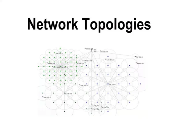
Network Topologies. Physical Categories. Three general categories describe the physical layout of networks according to “shape” Bus Ring Star. Physical Topology - Bus. Bus Single cable connecting all nodes on a network without addition of connectivity devices

E N D
Physical Categories • Three general categories describe the physical layout of networks according to “shape” • Bus • Ring • Star
Physical Topology - Bus Bus • Single cable connecting all nodes on a network without addition of connectivity devices • Every node shares total capacity of bus • Must be terminated at each end • Difficult to troubleshoot • Not fault-tolerant • Do not scale • More nodes sharing same capacity
Physical Topology - Ring • Forms circle • Each node connected to two adjacent nodes • Transmitted clockwise – one direction • Typically uses “token” to ensure that only one node is transmitting at a time • Not fault tolerant (one node down and the network is down) • Not scalable
Physical Topology - Star • All nodes on network connected through a central device • More fault tolerant – each node connected to central device • If central device fails – then segment using central device fails • Scalable
Implementation of Network Topologies • Local Area Network environments • Enterprise Network environments • Wide Area Network environments
Typical Local Area Network Topologies • Pure physical topologies not suitable for deployment in industry • Combination of features of the three basic physical topologies • Referred to as hybrid topologies
Typical Hybrid Physical Topologies in LANs • Star Wired Ring • Star Wired Bus • Daisy Chained • Hierarchical
Star Wired Ring • Star Wired Ring • IEEE 802.5 – token ring • Physical layout of star with token passing data transmission • Each node connected to central device such as hub • Data flows through each node via hub
Token Ring Implementation • Star wired ring • High Speed Token Ring standard • 100 Mbps • Use either TP or Fiber • Costly • Token passing • Determines which node (active monitor) can transmit
Token Ring Implementation continued • Active Monitor • 3 byte token • Picks up token and adds to it to become frame for transmission adding header, data, trailer • Circular in that token passed back to active monitor (originated transmission) • Either continues to transmit or issues free token
IEEE 802.5 • No collisions • Transmit • 4, 16 or 100 Mbps • 255 addressable stations on STP • 72 addressable stations on UTP • Connects via NIC to MAU (multistation access unit) – think hub • Highly fault tolerant – unused ports internally close loop
Token Ring Frames • IEEE 802.5 • Token fields – 3 bytes • Start Delimiter • Access Control • End Delimiter • Destination address • Source address • Data • Frame Check Sequence • Frame Status
IBM’s modification • Adds routing information used only by IBM applications
Star Wired Bus • Ethernet and Fast Ethernet networks • IEEE 802.3 • Nodes star connected to hubs • Hubs on single bus
Ethernet Implementation: CSMA/CD • Carrier Sense Multiple Access with Collision Detection • Access method of Ethernet • NICs listen on the network – when time passes and no signal then NIC determines can transmit as multiple nodes could make this assumption have Multiple Access – transmissions may interfere with each other – collisions possible
Collision Handling • Jamming signal • Collision domain • Mechanisms for ensuring that resending doesn’t generate another collision • Statistical algorithms • Time based algorithms • Switched Ethernet model employing logical network segments so can support more transmission without collisions
Daisy Chained • Daisy chain • Linked series of devices • Modular additions – connect hubs • Maximum number of hubs for transmission integrity
Device Definitions: Hub, Router, Bridge, Gateway • Hub: multiport repeater, regenerate digital signals, uplink port to connect to network backbone, used to connect multiple devices, operates at Physical Layer • Router: multiport device, can connect dissimilar LANs and WANs running at different transmission speeds with different protocols, determines best path for data transmission, operates at Network Layer
Definitions continued • Bridge: intelligent repeater, single input and single output, interpret data it retransmits; operates at Data Link Layer • Gateway: combination of networking hardware and software; connects two different types of networks; operates at several OSI model layers
Physical Topologies : Enterprise Wide Networks • Backbone networks • Serial • Distributed • Collapsed • parallel