Download
1 / 73
730 likes | 747 Vues
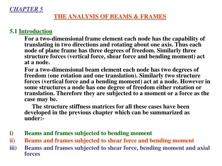
CHAPTER 5 THE ANALYSIS OF BEAMS & FRAMES 5.1 Introduction

E N D
CHAPTER 5 THE ANALYSIS OF BEAMS & FRAMES 5.1 Introduction For a two-dimensional frame element each node has the capability of translating in two directions and rotating about one axis. Thus each node of plane frame has three degrees of freedom. Similarly three structure forces (vertical force, shear force and bending moment) act at a node. For a two-dimensional beam element each node has two degrees of freedom (one rotation and one translation). Similarly two structure forces (vertical force and a bending moment) act at a node. However in some structures a node has one degree of freedom either rotation or translation. Therefore they are subjected to a moment or a force as the case may be. The structure stiffness matrices for all these cases have been developed in the previous chapter which can be summarized as under:- i) Beams and frames subjected to bending moment ii) Beams and frames subjected to shear force and bending moment iii) Beams and frames subjected to shear force, bending moment and axial forces
Following steps provide a procedure for the determination of unknown deformation, support reactions and element forces (axial forces, shear forces and bending moment) using the force displacement relationship (W=K). The same procedure applies both to determinate and indeterminate structures. 5.2 PROCEDURE TO ANALYSE BEAMS AND FRAMES USING DIRECT STIFFNESS METHOD 5.2.1. Identifying the components of the structural system or labeling the Structures & Elements. As a first step, divide the structure into some finite number of elements by defining nodes or joints. Nodes may be points of supports, points of concentrated loads, corners or bends or the points where the internal forces or displacements are to be determined. Each element extends between the nodes and is identified by arbitrary numbers (1,2,3). a) Structure Forces and Deformations At a node structure forces are assumed to act in their positive direction. The positive direction of the forces is to the right and upward and positive moments and rotations are clockwise. Start numbering the known forces first and then the unknown forces.
Structures Forces not acting at the joints Stiffness method is applicable to structures with structure forces acting at nodes only. However if the structure is subjected to concentrated loads which are not acting at the joints or nodal points or if it is subjected to distributed loads then equivalent joint loads are calculated using the following procedure. i) All the joints are considered to be fixed. [Figure-5(b)] ii) Fixed End Moments (FEM’s) and Reactions are calculated using the formulae given in the table as annex-I iii) If more than one FEM and reactions are present then the net FEM and Reaction is calculated. This is done by algebric summation. [Figure-5(c)] Equivalent structure forces or loads at the joints/nodes are obtained by reversing the signs of net FEM’s & Reactions. [Figure-5(d)] or Reversing the signs of Net FEM’s or reaction gives the equivalent structure loads on the joints/nodes. v) Equivalent element forces are calculated from these equivalent structure loads using equation 5.2, 5.3 and 5.4 as explained in article number 5. vi) Final element forces are obtained by the following equation w = wE + wF
wherewE = Equivalent element forceswF = Element forces while considering the elements to be fixed.
b) Element Forces Specify the near and far end of each element. Draw free body diagram of each member showing its local co-ordinate and element forces. Arbitrary numbers can identify all the element forces of the structure. 5.2.2. Calculation of Structure Stiffness Matrices of the members Properties of each element like its length, cross-sectional area, moment of inertia, direction cosines, and numbers identifying the structure forces acting at its near and far ends can be systematically tabulated. Using values of these parameters in equation 4.53 structure stiffness matrix of each member can be formed by applying equation 4.54,4.55 and 4.56 depending upon the situation. 5.2.3. Formation of Structure Stiffness Matrix of the Entire Structure According to the procedure discussed in chapter 3 article 3.1.3 stiffness matrix [K] of the entire structure is formed. 5.2.4. Calculation of Unknown Structure Forces and Displacements Following relation expresses the force-displacement relationship of the structure in the global coordinate system: [W] = [K] [] Where [W] is the structure load vector [K] is the structure stiffness matrix [] is the displacement vector
Partitioning the above equation into known and unknown portions as shown below: Where Wk = known loads Wu = unknown loads u = unknown deformation k = known deformation Expansion of the above leads to the following equation. [Wk] = [K11] [u] + [K12] [k] --------------------- (A) [Wu] = [K21] [u] + K22k --------------------- (B) As k = 0 So, unknown structure displacement [u] can be calculated by solving the relation (A), which takes the following form. [u] = [K11]-1 [Wk] ---------------------- (C) Unknown structure force i.e. reactions can be calculated by solving equation B which takes the following form Wu = [K21] [u] ---------------------- (D)
5.2.5. Calculation of element forces: Finally element forces at the end of the member are computed using the following equation (E). w = k = T w = kT --------------- (E) where [w] is the element force vector [kT] is the product of [k] and [T] matrices of the element where [w] is the element force vector [kT] is the product of [k] and [T] matrices of the element [] is the structure displacement vector for the element. Following are the [kT] matrices for different elements used in the subsequent examples. Case-I Beam/frame subjected to bending moment only
Case-II Beams subjected to Shear Forces & Bending Moment Case-III For frame element subjected to axial force, shear force and bending moment.
Plotting bending moment and shearing force diagrams: Bending moment and shearing force diagrams of the structure are plotted using the element forces calculated in step-5. Examples on the next pages have been solved using the above-mentioned procedure.
5.3 ILLUSTRATIVE EXAMPLES EXAMPLE 5.1 Solve the beam shown in the figure using stiffness method. Solution Numbering element and structure forces
Equivalent joint loads are : Calculating structure stiffness matrices of element Following table lists the properties needed to form structure stiffness matrices of elements.
Structure stiffness matrices are: Forming structure stiffness matrix of the entire structure Using relation [K] = [K]1 + [K]2 + [K]3 structure stiffness matrix of the entire structure is:
Finding unknown deformations Unknown deformations are obtained by using the following equation [D] = [K]-1 [W]
Calculating element forces Using relation [w]=[kT][D] we get
Actual forces on the structure are obtained by superimposing the fixed end reactions on above calculated forces.
EXAMPLE 5.2 Analyse the frame shown in the figure using stiffness method. Solution Numbering element forces and deformations
Finding Fixed end moments and equivalent structure load Equivalent Joint Loads
Calculating structure stiffness matrices of elements. Following table shows the properties of the elements required to form structure stiffness matrices of elements. Structure stiffness matrices of both elements are: 2 1 2 1 1 3 1 3
Forming structure stiffness matrix for the entire structure. Structure stiffness matrix for the entire frame is obtained using relation [K] = [K]1 + [K]2 1 2 3 finding unknown deformation Unknown deformation can be calculated by using equation []u = [K11]-1 [W]k This can be done by partitioning the structure stiffness matrix into known and unknown deformations and forces
[u] = [K11]-1[Wu] Finding Unknown Reactions Unknown reactions can be calculated using the following equation.
W=WF+WE Calculating element forces(Moments) Using relation
OR Actual forces acting on the structure can be found by superimposing the fixed end reactions on the forces calculated above.
EXAMPLE 5.3 Analyse the shown beam using direct stiffness method. Beam subjected to shear and moment. STEP-1 Numbering the forces and deformations
Equivalent joint loads = Calculating Structure Stiffness Matrices of Elements Following table shows the properties of the elements required to form structure stiffness matrices of elements
From structural elements Member-1 1 2 4 5 Member-2 2 3 5 6
Forming structure stiffness matrix for the entire structure Structure stiffness matrix for the entire beam is obtained using the relation [K] = [K]1 + [K]2 Finding unknown deformations Unknown deformation can be calculated using equation [u] = [K11]-1 [Wk] This can be done by partitioning the structure stiffness matrix into known and unknown deformations and forces.
Using Equation [u] = [K11]-1 [Wk] Finding Unknown Reactions Unknown reactions can be calculated using the following equation [W]u = [K]21 []u
W = WE + WF Since all the deformations are known to this point we can find the element forces in each member using the relation [w]m = [kT]m []m Member-1: Superimposing the fixed end forces for member-1 on the above w’s we get w = wE + wF
Member 2 : Superimposing the fixed end forces
OR w = wE +wF
EXAMPLE 5.4 Analyse the frame by STIFFNESS METHOD
Finding the structure stiffness matrices of elements. Next we will calculate the structure stiffness matrices for each element using the properties of members tabulated in below where E = 29000 ksiI = 100 inch4 and A = 5 inch2 (same for all members):
For member-1 we have 10 1 11 2 12 3
For member-2 1 4 2 5 3 6
For member-3 4 7 5 8 6 9 Finding structure stiffness matrix for the entire frame. Using relation [K] = [K]1+[K]2+[K]3 we get the following structure stiffness matrix. (See next slide)
Finding unknown deformations Unknown deformation can be calculated using equation [Du] = [K11]–1[Wk] This can be done by partitioning the structure stiffness matrix into known and unknown deformations and forces. Unknown deformations can be calculated using the equation ; [D]u=[K11]-1[W]k Solving the above equation we get ,