Download
1 / 8
100 likes | 459 Vues
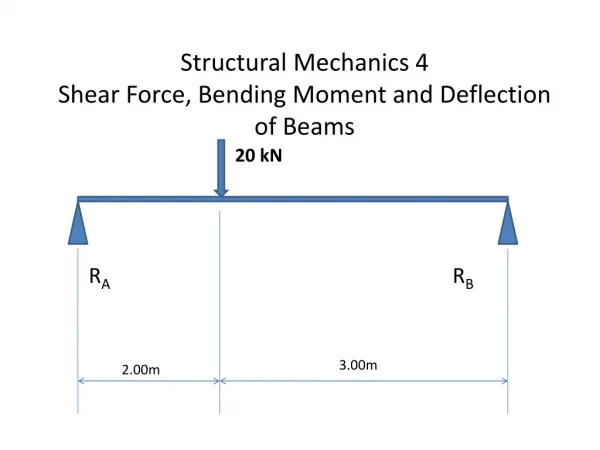
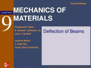
Chapter 12 Deflection of Beams and Shafts. Elastic Curve. The deflection diagram of the longitudinal axis that passes through the centroid of each cross-sectional area of the beam is called the elastic curve

E N D
Elastic Curve • The deflection diagram of the longitudinal axis that passes through the centroid of each cross-sectional area of the beam is called the elastic curve • In order to sketch the elastic curve it is necessary to know how the slope or displacement is restricted at various types of supports • Can use the beam moment diagram to determine if beam is concave upward (positive moment) or concave downward (negative moment)
Beam Parameters • v, x, and "localized" y axes • Differential element having an undeformed width dx and ds at a distance y from the neutral surface
Moment-Curvature Relationship • Relationship between internal moment, M, and radius of curvature, ρ
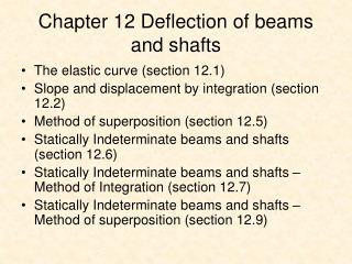
Slope and Displacement by Integration • The elastic curve for a beam can be expressed mathematically as v = f(x) • Recognizing that dv/dx will be very small, its square will be negligible compared to one
Sign Conventions • Positive deflection, v, is upward • Positive slope, θ, is measured counterclockwise when x is positive to the right (positive increases in dx and dv in x and v create an increased θ that is counterclockwise) • By assuming dv/dx to be very small, the horizontal length of the beam's axis and the arc of its elastic curve will be about the same, ds is approximately equal to dx - points on the elastic curve are assumed to displace vertically, and not horizontally • Since the slope angle will be very small, its value in radians can be determined directly from θ≈ tan θ = dv/dx
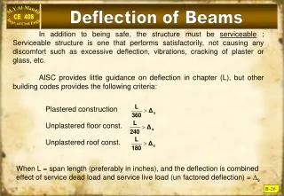
Boundary and Continuity Conditions • Boundary conditions must be evaluated in order to determine the constants of integration • If a single x coordinate cannot be used to express the equation for the beam's slope or the elastic curve, then continuity conditions must be used to evaluate some of the constants of integration • Problems, pg 587
Superposition • The differential equation EI d4v/dx4 = -w(x) satisfies the two necessary requirements for applying the principle of superposition • The load w(x) is linearly related to the deflection v(x) • The load is assumed not to change significantly the original geometry of the beam or shaft • As a result, the deflections for a series of separate loadings acting on a beam may be superimposed (added) • See Appendix C, Slope and Deflections of Beams, pg 808 and the FE Reference Handbook, pg 39 (in the Mechanics of Materials section) • Problems, pg 624