Download
1 / 72
920 likes | 1.8k Vues
Chapter 12 Deflection of beams and shafts. The elastic curve (section 12.1) Slope and displacement by integration (section 12.2) Method of superposition (section 12.5) Statically Indeterminate beams and shafts (section 12.6)

E N D
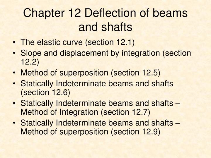
Chapter 12 Deflection of beams and shafts • The elastic curve (section 12.1) • Slope and displacement by integration (section 12.2) • Method of superposition (section 12.5) • Statically Indeterminate beams and shafts (section 12.6) • Statically Indeterminate beams and shafts –Method of Integration (section 12.7) • Statically Indeterminate beams and shafts –Method of superposition (section 12.9)
ELASTIC CURVE • The deflection diagram of the longitudinal axis that passes through the centroid of each cross-sectional area of the beam is called the elastic curve, which is characterized by the deflection and slope along the curve. E.g. Fig. 12-1
ELASTIC CURVE • Moment-curvature relationship: • Sign convention: Fig. 12-2 Fig. 12-3 Fig. 12-4
1 ρ ε y = – 1 ρ M EI = 1 ρ σ Ey = – ELASTIC CURVE • Consider a segment of width dx, the strain in are ds, located at a position y from the neutral axis is ε = (ds’ – ds)/ds. However, ds = dx = ρdθ and ds’ = (ρ-y) dθ, and so ε = [(ρ – y) dθ – ρdθ ] / (ρdθ), or Comparing with the Hooke’s Law ε = σ / E and the flexure formula σ = -My/I We have or Fig. 12-5
1 ρ 1 ρ d2v / dx2 [ 1 + (dv/dx)2 ] 3/2 d2v / dx2 [ 1 + (dv/dx)2 ] 3/2 = = M EI d2v dx2 = ≈ SLOPE AND DISPLACEMENT BY INTEGATION Kinematic relationship between radius of curvature ρ and location x: Then using the moment curvature equation, we have Or M = EIv” Note: M is a function of x Note: V is a function of x Note: w is a function of x Since V = dM/dx, so V = EIv”’ Also –w = dV/dx, so –w = EIv”” The above three equations will be used to find the elastic curve by integration
SLOPE AND DISPLACEMENT BY INTEGATION (CONT.) Sign convention: Fig. 12-8
SLOPE AND DISPLACEMENT BY INTEGATION (CONT.) Boundary Conditions: • The integration constants can be determined by imposing the boundary conditions, or • Continuity condition at specific locations Table 12 -1
METHOD OF SUPERPOSITION • Necessary conditions to be satisfied: • The load w(x) is linearly related to the deflection v(x), • The load is assumed not to change significantly the original geometry of the beam of shaft. • Then, it is possible to find the slope and displacement at a point on a beam subjected to several different loadings by algebraically adding the effects of its various component parts.
STATISTICALLY INDETERMINATE BEAMS AND SHAFTS • Definition: A member of any type is classified statically indeterminate if the number of unknown reactions exceeds the available number of equilibrium equations. • e.g. a continuous beam having 4 supports Fig. 12-34
STATISTICALLY INDETERMINATE BEAMS AND SHAFTS (CONT.) • Strategy: • The additional support reactions on the beam or shaft that are not needed to keep it in stable equilibrium are called redundants. It is first necessary to specify those redundant from conditions of geometry known as compatibility conditions. • Once determined, the redundants are then applied to the beam, and the remaining reactions are determined from the equations of equilibrium.