Download
1 / 21
230 likes | 351 Vues
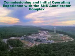
Commissioning Experience for the SNS Linac. A. Aleksandrov , S. Assadi, I. Campisi, P. Chu, S. Cousineau, V. Danilov, G. Dodson, J. Galambos, D.Jeon, S.Henderson, N. Holtkamp, L.Kravchuk, S. Kim, M. Plum, M. Stockli, E. Tanke ORNL, Oak Ridge, TN 37830 USA. Introduction: the SNS Project.

E N D
Commissioning Experience for the SNS Linac A. Aleksandrov, S. Assadi, I. Campisi, P. Chu, S. Cousineau, V. Danilov, G. Dodson, J. Galambos, D.Jeon, S.Henderson, N. Holtkamp, L.Kravchuk, S. Kim, M. Plum, M. Stockli, E. Tanke ORNL, Oak Ridge, TN 37830 USA
Introduction: the SNS Project Parameters: P beam on target 1.44MW I beam aver. 1.44mA Beam energy 1 GeV Duty factor 6% Rep. rate 60Hz Pulse width 1ms
DTL CCL RFQ (4) (6) (1) 86.8 MeV 2.5 MeV SNS Linac Layout 402.5 MHz 805 MHz HEBT MEBT To Ring and TGT DTL CCL SRF, ß=0.61, 0.81 RFQ Injector 1000 MeV 86.8 MeV 186 MeV 2.5 MeV Normal conducting linac 157 MeV 186 MeV
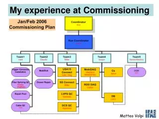
Commissioningruns Run #1 - Front End - beam stop for design beam power - 800 hours of operation (24/7) Run #2 - Front End & DTL tank 1 - beam stop and radiation shield for design beam power - 1136 hours of operation (24/7) Run #3 - Front End & DTL tank 1,2,3 - Beam stop and radiation shield for reduced beam power (50us, 1Hz) - 288 hours of operation (24/7) Run #4 - Front End, DTL , CCL modules 1,2,3 - Beam stop and radiation shield for reduced beam power (50us, 1Hz) - in progress
H- Ion source and LEBT Radio frequency, multi-cusp ion source. Electrostatic low energy beam transport line Electrostatic pre-chopper in the LEBT Current [mA] Ion source availability: Run #1 : 85.6% Run #2 : 92.4% Run #3 : 97.8% Life time test at hot spare test 1.2ms, 60Hz (7% duty factor)
402.5 MHz four-vane RFQ RFQ transmission vs. RF power Simulations (blue) and measurements (red) Output energy measured by Time Of Flight in MEBT = 2.45MeV (2% below design) During run#2 experienced resonant frequency shift of 500kHz. Returned to operation after retuning the cavity.
2.5MeV MEBT Schematic MEBT Layout RMS beam envelope in MEBT. Simulation (solid) and wire scanner measurements (dots). Beam current after RFQ (red), MEBT (blue)
Measured emittance after MEBT Design value = .3 mm mrad (RMS normalized) Dependance of RMS emittance upon peak beam current Beam emittance after MEBT. Vertical (top) and horizontal (bottom)
Chopping structure MEBT chopper (10ns, 1e-4) 38 mA LEBT chopper (50ns, 1e-2) current time 945 ns period time Chopping Measured effect of chopper on the beam(LEBT top, MEBT bottom )
402.5 MHz DTL withpermanent magnet focusing RF tuning: C.Deibele, THP65
Setting DTL phase and amplitude DTL phase scan. Measured dependence of beam phase at tank exit vs. tank RF phase compared with simulations (solid lines) for different RF amplitudes (different colors). DTL acceptance scan. Transmission through energy degrade vs. tank phase
Measured emittance after DTL tank 1 Vertical normalized RMS emittance = 0.3 mm*mrad Horizontal normalized RMS emittance = 0.4 mm*mrad Absolute calibration of horizontal scanner is under investigation due to discrepancy with wire scanner measurements
Beam trajectory after correction Beam trajectory from RFQ exit to CCL beam dump. Vertical scale +- 1mm
Transverse beam profile and losses in CCL Beam profile measured by wire scanner in CCL4 Beam loss pattern in DTL-CCL
Diagnostics performance • Beam position and phase monitors • Position resolution <.2um • Phase resolution <.5 deg • Beam current monitors • 1-2% accuracy for short pulses • Wire scanners • ~ 1000 dynamic range • Require individual bias adjustment depending on energy, beam current • Loss monitors • Commissioned but did not use • Other devices tested • Laser based profile monitor for superconducting linac • Laser based beam in gap measuring system • Fast Faraday cup
Summary • Successfully commissioned Front End, Drift Tube Linac, Coupled-Cavity Linac modules 1-3 • Demonstrated high power operation of Front End and Drift tube Linac tank #1 • Design requirements for peak current, energy are met for 50us pulse at 1Hz for warm linac • Developed tuning procedures, commissioned all diagnostics systems • Will commission last CCL module #4 together with Super Conducting Linac in summer 2005