Download
1 / 36
380 likes | 988 Vues
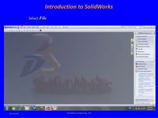
Introduction to SolidWorks. Draft 124. Dassault Systemes 3 – D and PLM software PLM - Product Lifecycle Management Building models on Computer Engineering Analysis and Design Production Market. SOLIDWORKS. Started in 1993 3D CAD : Creating complex parts and assemblies

E N D
Introduction to SolidWorks Draft 124
DassaultSystemes • 3 – D and PLM software • PLM - Product Lifecycle Management • Building models on Computer • Engineering Analysis and Design • Production • Market.
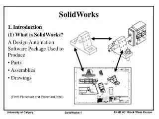
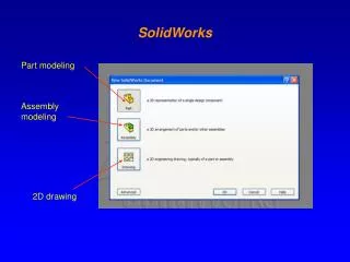
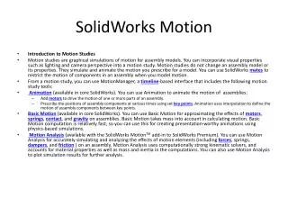
SOLIDWORKS Started in 1993 3D CAD : Creating complex parts and assemblies 2D Drawings : Working drawings for production Modeling tools : Feature Recognition, Reverse Engineering Data Management Simulation Presentation : Photoworks
Draft 124 • Understand and implement principles of Technical Drawing to create 3D parts, assemblies and 2D working drawings on the computer. • Learn to use various capabilities of the software SolidWorks to create 3D parts, assemblies and 2D drawings.
Online Resources SW Community forums. http://forum.solidworks.com Blogs. blogs.solidworks.com You tube
Dimensioning Revisited Chapter 9
Understanding Dimensioning • Drawings for products must be dimensioned so that production personnel all over the world can make mating parts that will fit properly when assembled or when used to replace parts • Dimensions are given in the form of distances, angles, and notes regardless of the dimensioning units being used
Aspects of Good Dimensioning • The ability to create good dimensions requires: • Technique of dimensioning • Placement of dimensions manufacturing, measurement, inspection, functioning. • Choice of dimensions
Using Dimension and Extension Lines • Dimensions should be lined up and grouped together as much as possible
Using Dimension and Extension Lines • When extension lines or center lines cross visible object lines, gaps should not be left in the lines
Leaders • A leader is a thin solid line directing attention to a note or dimension and starting with an arrowhead or dot • Leaders should be at an angle of 30-60˚
Placing Dimensions • Never letter a dimension value over any line on the drawing • In a group of parallel dimension lines, the dimension values should be staggered • Do not crowd dimension figures into limited spaces making them illegible
Placing Dimensions • Place dimensions between views when possible, but only attached to a single view • Dimensions should not be placed on a view unless doing so promotes the clarity of the drawing
Placing Dimensions • When a dimension must be placed in a hatched area or on the view, leave an opening in the hatching or a break in the lines for the dimension value
Placing Dimensions • Avoid dimensioning to hidden lines • Do not attach dimensions to visible lines where the meaning is not clear • Notes for holes are usually placed where you see the circular shape of the hole • An external cylindrical shape is dimensioned where it appears rectangular
Placing Dimensions • Give dimensions where the contours of the object are defined
Superfluous Dimensions • All necessary dimensions must be shown but avoid giving unnecessary dimensions • Do not repeat dimensions on the same view or on different views, or give the same information two different ways
Dimensioning Angles • You should dimension angles by specifying the angle in degrees and a linear dimension
Dimensioning Arcs • A circular arc is dimensioned in the view where you see its true shape by giving the value for its radius preceded by the abbreviation R
Fillets and Rounds • Individual fillets and rounds are dimensioned like other arcs • If there are only a few and they are obviously the same size, giving one typical radius is preferred • Fillets radii can also be given in a general note
Which is the mating dimension in figure (a) Which is the mating dimension in figure (b)
Notes • It is usually necessary to supplement the direct dimensions with notes • Notes should be worded to allow only one interpretation • Notes should be lettered horizontally
Tabular Dimensions Several parts with Similar features Different dimensions.