Download
1 / 40
430 likes | 1.39k Vues
Curved Surfaces. CSE167: Computer Graphics Instructor: Steve Rotenberg UCSD, Fall 2006. Curve Evaluation. p 1. Find the point x on the curve as a function of parameter t :. •. x ( t ). p 0. p 2. p 3. de Casteljau Algorithm. p 1. We start with our original set of points

E N D
Curved Surfaces CSE167: Computer Graphics Instructor: Steve Rotenberg UCSD, Fall 2006
Curve Evaluation p1 • Find the point x on the curve as a function of parameter t: • x(t) p0 p2 p3
de Casteljau Algorithm p1 • We start with our original set of points • In the case of a cubic Bezier curve, we start with four points p0 p2 p3
de Casteljau Algorithm p1 q1 q0 p0 p2 q2 p3
de Casteljau Algorithm q1 r0 q0 r1 q2
de Casteljau Algorithm r0 • x r1
Bezier Curve p1 • x p0 p2 p3
Derivatives • Finding the derivative (tangent) of a curve is easy:
Tangents • The derivative of a curve represents the tangent vector to the curve at some point
Bezier Surfaces • Bezier surfaces are a straightforward extension to Bezier curves • Instead of the curve being parameterized by a single variable t, we use two variables, s and t • By definition, we choose to have s and t range from 0 to 1 and we say that an s-tangent crossed with a t-tangent will represent the normal for the front of the surface 0,1 t 1,1 n 0,0 s 1,0
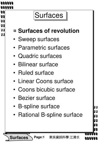
Curved Surfaces • The Bezier surface is a type of parametric surface • A parametric surface is a surface that can be parametrized by two variables, s and t • Parametric surfaces have a rectangular topology • In computer graphics, parametric surfaces are sometimes called patches, curved surfaces, or just surfaces • There are also some non-parametric surfaces used in computer graphics, but we won’t consider those now
Control Mesh • Consider a bicubic Bezier surface (bicubic means that it is a cubic function in both the s and t parameters) • A cubic curve has 4 control points, and a bicubic surface has a grid of 4x4 control points, p0 through p15 p12 p13 p8 t p9 p14 p4 p15 p5 p0 p10 p1 p11 p6 s p7 p2 p3
Surface Evaluation • The bicubic surface can be thought of as 4 curves along the s parameter (or alternately as 4 curves along the t parameter) • To compute the location of the surface for some (s,t) pair, we can first solve each of the 4 s-curves for the specified value of s • Those 4 points now make up a new curve which we evaluate at t • Alternately, if we first solve the 4 t-curves and to create a new curve which we then evaluate at s, we will get the exact same answer • This gives a pretty straightforward way to implement smooth surfaces with little more than what is needed to implement curves t (0.2, 0.6) s
Matrix Form • We saw the matrix form for a 3D Bezier curve is
Matrix Form • To simplify notation for surfaces, we will define a matrix equation for each of the x, y, and z components, instead of combining them into a single equation as for curves • For example, to evaluate the x component of a Bezier curve, we can use:
Matrix Form • To evaluate the x component of 4 curves simultaneously, we can combine 4 curves into a 4x4 matrix • To evaluate a surface, we evaluate the 4 curves, and use them to make a new curve which is then evaluated • This can be written in a compact matrix form:
Matrix Form • Cx stores the coefficients of the bicubic equation for x • Gx stores the geometry (x components of the control points) • BBez is the basis matrix (Bezier basis) • s and t are the vectors formed from the exponents of s and t • The matrix form is a nice and compact notation and leads to an efficient method of computation • It can also take advantage of 4x4 matrix support which is built into modern graphics hardware
Tangents • To compute the s and t tangent vectors at some (s,t) location, we can use:
Normals • To compute the normal of the surface at some location (s,t), we compute the two tangents at that location and then take their cross product • Usually, it is normalized as well n t x s
Bezier Surface Properties • Like Bezier curves, Bezier surfaces retain the convex hull property, so that any point on the actual surface will fall within the convex hull of the control points • With Bezier curves, the curve will interpolate (pass through) the first and last control points, but will only approximate the other control points • With Bezier surfaces, the 4 corners will interpolate, and the other 12 points in the control mesh are only approximated • The 4 boundaries of the Bezier surface are just Bezier curves defined by the points on the edges of the surface • By matching these points, two Bezier surfaces can be connected precisely
Tessellation • Tessellation is the process of taking a complex surface (like a bicubic patch) and approximating it with a set of simpler surfaces (like triangles) • In computer graphics, there are a lot of different types of complex surfaces one might want to tessellate, such as: • Parametric surfaces (such as Bezier surfaces) • Displacement mapped surfaces • Subdivision surfaces • Fractals • Procedural models • Implicit surfaces • We will look at the first two today
Uniform Tessellation • The most straightforward way to tessellate a parametric surface is uniform tessellation • With this method, we simply choose some resolution in s and t and uniformly divide up the surface like a grid • This method is very efficient to compute, as the cost of evaluating the surface reduces to approximately the same cost as evaluating a curve • However, as the generated mesh is uniform, it may have more triangles than it needs in flatter areas and fewer than it needs in highly curved areas
Adaptive Tessellation • Very often, the goal of a tessellation is to provide the fewest triangles necessary to accurately represent the original surface • For a curved surface, this means that we want more triangles in areas where the curvature is high, and fewer triangles in areas where the curvature is low • We may also want more triangles in areas that are closer to the camera, and fewer farther away • Adaptive tessellation schemes are designed to address these requirements
Mixed Tessellation • Some practical renderers use a mixed tessellation scheme • First, the original surface patch is adaptively subdivided into several subpatches, each approximately the same size (say around 10 pixels on a side) • Then, each of the subpatches (which is just a rectangular s,t range within the larger 0,1 rectangle) is uniformly tessellated to some size (say 10 x 10) • The result is that the curved surface is tessellated into triangles roughly the size of a single pixel • The bulk of the cost of the algorithm is in the uniform tessellation, which can be implemented in a very efficient way
Displacement Mapping • To add additional geometric detail to a tessellated surface, we can use displacement mapping • With this technique, a displacement map is stored, which is much like a texture map that stores a height value per texel instead of a color • As with texture mapping, we can assign a texture coordinate to each corner of the patch that allows us to position the displacement map onto the surface • This coordinate gets interpolated when we evaluate the position and normal of the patch for some (s,t) value • We can displace the position by the height value. The displacement is usually done along the computed patch normal • Once we’ve displaced our tessellated triangle mesh, we will need to recompute accurate normals, as they will change based on the displacements • To avoid geometry aliasing, we should really perform some sort of filtering on the height value (such as mipmapping)
Scan Conversion • The serial scan conversion technique we looked at earlier in the quarter requires expensive set-up computations in order to make the per-pixel cost very low, thus making it efficient for large triangles • Some surface renderers generate triangles smaller than a single pixel, or the size of a few subpixels in an antialiased rendering • For triangles this small, it is usually better to use different approaches in the scan conversion process • Also, as these micropolygons are so usually generated from uniform tessellations, other optimizations can be made to account for all of the shared vertices and edges between them
Transparency • Parametric surfaces and displacement mapping combine to add a powerful new set of features for describing complex geometry • Usually, renderers that support advanced features such as these will also have a more sophisticated technique for handling transparency and hidden surfaces than the techniques we’ve seen so far • High quality renderers generally don’t render the scene one primitive at a time • Instead, they must store the entire scene in memory at one time and process the rendering one pixel at a time • In this way, if we have many layers of transparent surfaces overlapping in complex ways, we don’t have to rely on sorting the primitives, which may be guaranteed to fail…
Scanline Rendering • Some renderers (such as ray tracers) truly render individual pixels one by one and can therefore render them in random order • Other renderes are organized to process the entire scene in a serial fashion, such as top to bottom, left to right • These are known as scanline renderers, as they process one horizontal scanline at a time
Scanline Rendering • With a scanline renderer, primitives (such as triangles) are first transformed and clipped/culled to device space • The clipping/culling removes any invisible triangles, and the remaining triangles are gathered together into a big array • Next, the array of primitives is sorted from top to bottom, based on the highest y value in the primitive • Then, the rendering begins, by looping in y from the top scanline down to the bottom • We maintain an active list of primitives, which are all of the primitives that intersect the current scanline • For each new scanline, we may add some new primitives to the list and remove some old ones • We also keep the active list sorted from left to right, based on the lowest x value in the primitive • To render a scanline, we loop through the active list, breaking it up into horizontal spans, where each span can have the individual primitives sorted in z
Surface Renderers • Curved surface renderers often use a scanline based approach combined with the mixed tessellation scheme • Surface patches are subdivided into roughly uniform sized subpatches, which are culled to the view frustum • The scanline algorithm then treats these subpatches as the primitives • When a new subpatch is added to the active list, it is uniformly tessellated into a grid of microtriangles, which can then be scan converted with special purpose techniques • This method allows the combination of complex surfaces, displacement maps, antialiasing, and transparency while being reasonably efficient with memory usage • Of course, one can also perform any lighting operations one wants to apply per microtriangle, and in fact, this tends to be the most expensive part of the rendering
Surface Renderers • High quality renderers need to be able to render extremely detailed scenes efficiently • The scanline approach combined with mixed tessellation is a powerful approach to rendering that has been used for many years in real applications • Renderers often allow arbitrary properties to be assigned to the corners of the patches, or otherwise mapped onto them • These properties are then used by user-programmable shaders that can implement texture mapping, lighting, displacement mapping, and other operations to come up with the final surface shape and pixel color • This fundamental approach is the one proposed in the REYES architecture (render everything you ever saw), back in 1984 • It is the backbone of Pixar’s RenderMan renderer, which has been used in numerous movies for the last 20 years • Only in the last 5 years has there been a serious push towards the even more sophisticated approaches of ray tracers and global illumination renderers, which we will look at later…
Other Curve Types • Curves • Hermite curves • Catmull-Rom curves • B-Splines • NURBS • Surfaces • B-Spline / NURBS • Trim curves • Subdivision surfaces • Implicit surfaces