Download
1 / 12
120 likes | 211 Vues
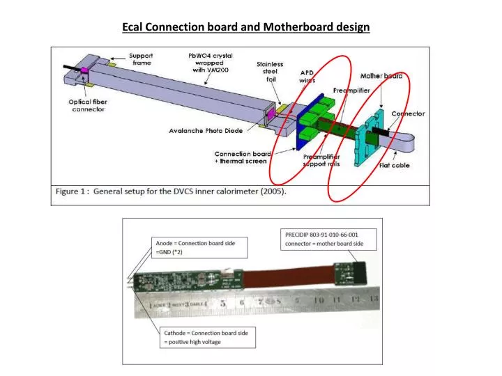
Ecal Connection board and Motherboard design. Connection Board. Motherboard. Connection Board. The connection board links the APD on one side and Preamplifier on the other side: Connection from the APDs to the Board is by 2 twisted wires.

E N D
Connection Board Motherboard
Connection Board • The connection board links the APD on one side and Preamplifier on the other side: • Connection from the APDs to the Board is by 2 twisted wires. • Connection from the Board to Amplifier is by 3 pin socket. • There are also preamplifier support rails soldered on the board to hold the amplifiers in place. • The board provides thermal screen and provides ground link between the APD and preamplifiers. 46 Crystals across ~ 736mm (29in) 16mm 16mm B A 10 Crystals high ~ 160mm (6.3in) 25mm 21 Crystals 21 Crystals C D 23 Crystals x 23 Crystals y 23 Crystals 111 Crystals per Quadrant Total Crystals = 444
Slotted Motherboard DVCS 2005 Inner Calorimeter Motherboard HPS ECal Motherboard
986mm (38.8in) 125mm (4.92in) B A Quadrant B Connectors Quadrant A Connectors 111 Crystals 111 Crystals 50mm 160mm (6.3in) Quadrant C Connectors C D Quadrant D Connectors 111 Crystals 111 Crystals 8-Pin Connectors High Voltage Connector 8-Pin Connector (HE804EN17YOA401) Preamp signals Low Voltage Connector 8-Pin Connector (Molex_43045-0612)
786mm (31in) Quadrant B Connectors Quadrant A Connectors B A 111 Crystals 111 Crystals 220mm (8.7in) 50mm HV/LV Connectors HV/LV Connectors C D 111 Crystals 111 Crystals Quadrant C Connectors Quadrant D Connectors 8-Pin Connectors High Voltage Connector (HE804EN17YOA401) Preamp signals Low Voltage Connector (Molex_43045-0612)
Slotted Motherboard 46 Crystals across ~ 736mm (29in) 16mm 16mm 80mm (3.15in) 5 Crystals high ~ 80mm (3.15in) 25mm 21 Crystals across ~ 336mm (13.2in) GND GND Board Cutout GND Signal Connector Footprint +5V GND 12.6mm -5V GND GND HV 6.3mm 16mm
Proposed non-slotted Motherboard • The preamplifier output signals have to be sandwiched between two ground strips (on the motherboard) to reduce crosstalk. • This increases routing complexity. • To reduce noise on the signals, the following Motherboard design is proposed: • Move the existing APD connector to the backside of the motherboard (side with the APD). • Put a LEMO connector on the frontside of the motherboard. • Connect directly to the readout boards from the from motherboard. To Readout Module Preamplifier Crystal Connection Board Motherboard
Backside View 46 Crystals across ~ 736mm (29in) 16mm 16mm 5 Crystals high ~ 80mm (3.15in) 80mm (3.15in) 25mm 21 Crystals across ~ 336mm (13.2in) GND GND Precidip 802-PP-NNN-10-001101 Connector Footprint (12.7mm X 8.5mm) GND Signal Lemo EPB.00.250.NTN Connector Footprint (7mm X7mm) +5V GND -5V GND GND HV 16mm
Frontside View 46 Crystals across ~ 736mm (29in) 16mm 16mm HV & LV Connectors 5 Crystals high ~ 80mm (3.15in) 80mm (3.15in) 25mm 21 Crystals across ~ 336mm (13.2in) LEMO EPB.00.250.NTN Connector Footprint (7mm X 7mm) Not to scale 16mm
Summary • Discussion of alternative motherboard design. • How does it affect Mechanical design by adding ~ 6inches separation between motherboard and connection board? • Slotted vs non-slotted • Pros • Easier design = Less labor during routing. • Reduce Signal Integrity concerns. • Access to individual crystal signal for readout. • Slotted motherboard is flimsier. • Cons: • Might need another “dummy” slotted board to support the preamp. • Lemo connectors ~ $10 each.