Download
1 / 38
550 likes | 789 Vues
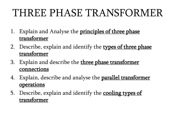
THREE PHASE TRANSFORMER. Explain and Analyse the principles of three phase transformer Describe, explain and identify the types of three phase transformer Explain and describe the three phase transformer connections Explain, describe and analyse the parallel transformer operations

E N D
THREE PHASE TRANSFORMER • Explain and Analyse the principles of three phase transformer • Describe, explain and identify the types of three phase transformer • Explain and describe the three phase transformer connections • Explain, describe and analyse the parallel transformer operations • Describe, explain and identify the cooling types of transformer
1. Principles of Three Phase Transformer When more power is needed, three transformers can be tied together. This is called three-phase.
Generating three- phase Three phase (3Ø) power is delivered from generator with 3 separate windings. These windings are equally spaced, with 120º apart.
How much is it stronger? It is stronger by 173.2 % = 1.732 = √3
Multiply √3 We calculate the total voltage of all 3 line of a 3 phase transformer by multiplying the voltage of each single winding(phase) by √3.Why?
The reason is the angles of each phase are always 120º apart. By using trigonometric formula
Basic Principle of a three phase transformer • The three cores are arranged at 120o from each other. • The primaries are connected to the three phase supply. • The primaries carry the currents IR, IY and IB producing the fluxes ΦR, ΦY and ΦB in the individual cores. • The common leg of the cores i.e. centre leg formed carries sum of the all three fluxes.+ ĪY + ĪB = 0, hence the sum of the three fluxes is also zero at any instant. Hence the centre leg does not carry any flux.
2. Types of 3Ø transformer Transformers for three-phase circuits can be constructed in two ways: • First, to take three single phase transformers and connect them into a three-phase bank. • Secondly, is to make a three- phase transformer consisting of three sets of windings wrapped on a common core. Both designs are in use today.
Three single- phase transformer bank NP1 NP2 NS2 NS1 NP3 NS3
Three- Phase Transformer NP3 NP2 NP1 NS3 NS1 NS2
3. 3 phase transformer connections Three- phase transformer can be tied together in • Wye connection • Delta connection
Simplified Wye connection Single -phase, 208V oven 120 V 120 V Single-phase, 120V fluorescent light 120 V Three-phase, 208V heavy machine
Three Phase Transformer Connection Delta -Wye (Δ-Y) Wye / Wye (Y-Y) Wye /Delta (Y-Δ) Delta-Delta (Δ-Δ)
Wye-Wye Connection a’ a a a’ Vфp Vфs b’ b NP1 NS1 + + Np2 Ns1 Np1 Ns2 The overall voltage ratio is b b’ VLp VLs + + Np3 Ns3 Vфp Vфs VLS NP2 NS2 VLP - - c’ c c c’ NP3 NS3 n n
Wye-Delta Connection a a a’ Vфp b NP1 NS1 + Np2 Np1 The overall voltage ratio is c’ b b’ VLp + + Ns2 + Np3 Vфp VLS NP2 NS2 VLP Ns3 b’ Vфs - - VLs Ns1 Vфs c c c’ a’ NP3 NS3 n
Delta-Wye Connection a a’ Vфs a’ + + VLP Vфp + + NP1 NS1 + Vфs NS2 NS1 - The overall voltage ratio is - - b c’ VLS VLS NS3 NP2 NS2 + c c + + b’ b’ - - VфP NP2 VLP c’ NP3 NS3 - NP3 b NP1 n a
Delta-Delta Connection a a’ + Vфp VLP VLs NP1 NS1 Vфs - b’ b The overall voltage ratio is NP2 NS2 c’ c Ns2 a a’ + + + - VLs Vфp VLp NP3 b’ - Ns1 NP1 Ns3 NP3 NS3 Vфs - - NP2 + b c’ c
4. Parallel transformer operations • It is economical to install numbers of smaller rated transformers in parallel than installing a bigger rated electrical power transformers for the following main advantages:
To maximize electrical power system efficiency • Generally electrical power transformer gives the maximum efficiency at full load. • If we run numbers of transformers in parallel, we can switch on only those transformers which will give the total demand by running nearer to its full load rating for that time. • When load increases, we can add another transformer connected in parallel to fulfil the total demand. • In this way we can run the system with maximum efficiency.
To maximize electrical power system availability • If numbers of transformers run in parallel, we can shutdown any one of them for maintenance purpose. • Other parallel transformers in system will serve the load without total interruption of power.
To maximize power system reliability • if any one of the transformers run in parallel, is tripped due to fault of other parallel transformers is the system will share the load, hence power supply may not be interrupted if the shared loads do not make other transformers over loaded.
To maximize electrical power system flexibility • There is always a chance of increasing or decreasing future demand of power system. • If it is predicted that power demand will be increased in future, there must be a provision of connecting transformers in system in parallel to fulfil the extra demand because, it is not economical from business point of view to install a bigger rated single transformer by forecasting the increased future demand as it is unnecessary investment of money. • Again if future demand is decreased, transformers running in parallel can be removed from system to balance the capital investment and its return.
Conditions for Parallel Operation of Transformers When two or more transformers run in parallel, they must satisfy the following conditions for satisfactory performance. These are the conditions for parallel operation of transformers. • Same voltage ratio of transformer. • Same percentage impedance. • Same polarity. • Same phase sequence.
5. Cooling types of transformer • The main source of heat generation in transformer is its copper loss or I2R loss. Although there are other factors contribute heat in transformer such as hysterysis & eddy current losses but contribution of I2R loss dominate them. • If this heat is not dissipated properly, the temperature of the transformer will rise continually which may cause damages in paper insulation and liquid insulation medium of transformer.
So it is essential to control the temperature with in permissible limit to ensure the long life of transformer by reducing thermal degradation of its insulation system. • In electrical power transformer we use external transformer cooling system to accelerate the dissipation rate of heat of transformer. • There are different transformer cooling methods available for trans former:
ONAN Cooling of Transformer • This is the simplest transformer cooling system. • The full form of ONAN is "Oil Natural Air Natural".
ONAF Cooling of Transformer • The full form of ONAF is "Oil Natural Air Forced".
OFAF Cooling of Transformer • OFAF means "Oil Forced Air Forced" cooling methods of transformer.