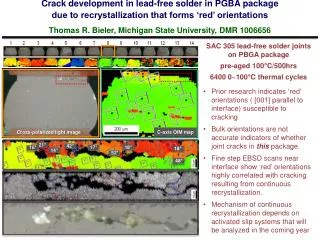
Download
1 / 31
320 likes | 831 Vues
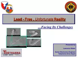
Lead-Free ( Pb -free) Electronics & Finishes 29 April 2014. AFMC AFSC 448 th 415 SCMS/GUMBB DSN 586-1442. Overview. Introduction Lead-free – the issue Lead-free Actual Cases W ay Forward Risk Mitigation Improvements Summary. 5/9/2014. 2. Introduction.

E N D
Lead-Free (Pb-free) Electronics & Finishes29 April 2014 AFMC AFSC 448th 415 SCMS/GUMBBDSN 586-1442
Overview Introduction Lead-free – the issue Lead-free Actual Cases Way Forward Risk Mitigation Improvements Summary 5/9/2014 2
Introduction What if your repair line discovered Pb-free parts in bins? Aircraft Control Amp 5/9/2014 3
Introduction What if your repair line discovered whiskers? Aircraft Fuel Quantity Indicator 5/9/2014 4
Principle #1 – Not just Solder Soldering • Electronics has established reliability baseline with SnPb solder (63% Tin, 37% Lead) • There is no direct replacement or substitution that “gets the lead out” Electronic Components • Lead-free electronic components are unavoidable Surface Plating • Pure tin plating is attractive, low cost, and environment “green” Not Just Solder
Principle #2 – Not just Whiskers Tin Whiskers – random in nature Cross Contamination – material mixing in soldering Solder Temperatures– collateral heating (over-heating) Pb-free Solder Joints – “New” compared to Tin-Lead (SnPb) Not Just Whiskers
Not Just Solder or Whiskers Risk Assessment for Pb-free Processes per LSA SOLD-08-07 Frequency of Occurrence is X Times the SnPb Baseline LSA = Lead (not Pb but lead as in leader) Standardization Activity
Solder Temperatures Processing Temperatures Phenomenon Thermal Simulation of 208 PQFP Blue = 30 - 50 oC Red = 225 – 250 oC • Soldering Iron set to 315 oC (600 oF) • Solder Pot set to 245 oC (473 oF)
Know What To Look For Become familiar with these designations for ELECTRONIC COMPONENTS (J-STD-609) • Traditional Tin-Lead Construction/Component Leg Finish • e0 contains lead (> 0.1 wt %), traditional Sn/Pb solder tinning • These Designations are Lead-free (Pb-free) • e1 Sn/Ag/Cu (shall not be included in category e2) • e2 Sn alloys with no Bi or Zn, excluding Sn/Ag/Cu • e3 Sn • e4 Precious metal (Ag, Au, Ni/Pd, Ni/Pd/Au) [no Sn] • e5 Sn/Zn, Sn/Zn/X (no Bi) • e6 Contains Bi • e7 Low temperature solder containing Indium (no Bi) • e8 and e9 symbols are unassigned Know Your Repair Process and Component Inventory
Hill AFB Affected Product – Resolved through Risk Analysis Aircraft Fuel Quantity Indicator 5/9/2014 11
Hill AFB Aircraft Fuel Quantity Indicator - Whiskers Product designed/manufactured prior to 2000 “Spring” part is not an electrical part Example of whisker mitigation technique effectiveness – solder dip Aircraft Fuel Quantity Indicator 5/9/2014 12
Hill AFB Aircraft Alpha Computer – Critical Safety ItemPre-RoHS Parts in Inventory 225V 400ma Diode JANTXV1N645-1 NSN 5961-01-071-6704 Potentially Fused Tin (Sn) Pb below 2% on 2 samples Example where legacy construction is lead-free Lead-free/RoHS transition began ~2003 and these parts are manufactured 1998 Fusing (reflow above 232°C where the tin fully melts) within a short time frame after plating – mitigates whiskers Yesterday’s traditional construction, Today’s lead-free e3, JESD Class 2 5/9/2014 13
Gold Leads Digital Microcircuit Buffer/Driver IC 55462H 55462HMQB NSN 5962-01-123-3164 71% Gold Legs 0.2% Lead (Pb) Therefore Pb-free Example where legacy construction is lead-free DLA Case # DSCC-FM-09-15764 to add supplier – no issue with 339 Yesterday’s traditional construction, Today’s lead-free e4, JESD Class 2 5/9/2014 14
ConsciousLead-free Approval through DLA 339 Terminals: Copper alloy, matte tin plated over nickel barrier (per JESD 201). Only available in lead-free Supplier Grayhill (distributor not manufacturer) 500V 3 A Switch 2 through 12 position 0.28“ through 1.28“ NSN 5930-01-7015 Cancellation of MIL-PRF-83504, Which specifies 3% lead on DIP switch component legs Engineering Authority Approved with full awareness Satellite Ground Station Application Case Number: DSCC-FM-11-02139 October 2010 5/9/2014 15
Lead-free Part Meets Spec 20V 150ma Diode per drawing 033549 (last dwg Rev 1991) NSN 5961-01-105-4854 e4 - Ag, Au, or Ni/Pd instead of tin Spec does not prohibit lead-free Dwg 033549 “3.3.1 Lead Finish: Leads shall be solderable (tinned or gold plated)” DLA: “No 339s or engineering authority activity that accepted this part” MXW Technician: “Cannot purge/QDR the Integrated Parts Vendor bins, because we do not have anything in writing that says we can't use lead free” 5/9/2014 16
Supplier Solder Dipped Lead-free to Meet Spec e1 - Sn/Ag/Cu 96.5 Sn 3.0Ag 0.5Cu Contractor dipping In SnPb bath before delivery - mismarked Part approved through DLA 339 and Pb-free not part of decision 150V Tantalum Electrolytic Capacitor per M39006/01 NSN 5910-00-009-6732 DLA Case # DSCC-FM-10-42179 M39006/01 3.4.3 Pure tin. The use of pure tin, as an underplate or final finish, is prohibited both internally and externally. Tin content of capacitor and solder shall not exceed 97%, by mass. Tin shall be alloyed with a minimum of 3% lead. 6.11 Tin whisker growth. The use of alloys with tin content greater than 97%, by mass, may exhibit tin whisker growth problems after manufacture. 5/9/2014 17
Manufacturer’s Data Sheet Does Not Show an e1 Option e1 - Sn/Ag/Cu 96.5 Sn 3.0Ag 0.5Cu Approved as a replacement by OC-ALC (422nd) & WR-ALC (407th) Specification may not prohibit lead-free 600V 1 A Diode 1N5061 80131-RELEASE5452 0.032 leg diameter NSN 5961-00-111-4795 Potential replacement 200V 3 A Diode JANTX1N5417 0.040 leg diameter DLA Case # DSCC-FM-10-17097 NSN 5961-00-403-4545 “DLAD Clause 52.211-9063, 'Unit Package Marking Requirement for Component Lead Finish', Applies” Part is Vishay per DLA but Vishay does not show an e1 version per datasheet, 29 samples measure e0 80131-RELEASE5452 Specification (1967) – “no fragile whiskers” Latest Vishay datasheet - E3 suffix meets JESD 201 class 1A whisker test, HE3 suffix meets JESD 201 class 2 whisker test An item authorized for procurement as a result of a formal item reduction study & accepted as a replacement 5/9/2014 18
Lead-free components are unavoidable – Prohibiting lead-free is unrealistic and not effective Lead-free is not a brand new threat, increased threat “Legacy” Lead-free parts have been in Air Force processes for over 20 years – (e.g., fused tin, gold leads) Depot Solder is traditional tin-lead (63Sn37Pb) Discovery relies on the depot technician – all trained but skills/enforcement vary Estimated Lead-free Inventory at Hill AFB is 5% (not including “legacy” lead-free) Air Force Way Forward
Follow Navy Lead • Naval Surface Warfare Center Instruction NSWCCRANEINST 4855.18C • Guides to solder components with pure tin finishes with SnPb solder, if … • …approval obtained from the engineering authority and program manager • Engineering authority approval = risk analysis • Air Force Activity • Adopting Navy soldering TO – TO 00-25-234 (AF) converted to 00-25-259 (Navy) • Air Force Lead-free Electronics Team (LFET)
Navy InstructionNSWCCRANEINST 4855.18C document, table 1 Risk Management for Pb-free Solder Technology Repair Processes 1 and 3
Risk Assessment Risk Assessment for Pb-free Processes per LSA SOLD-08-07 Frequency of Occurrence is X Times the SnPb Baseline LSA = Lead (not Pb but lead as in leader) Standardization Activity
Get Control • Assign a Control Level per SAE/GEIA-STD-0005-2 • Different based on criticality (aircraft and ground systems may have different control levels) • Control Level 2C for Aircraft avionics is a starting place • Know your Weapon System Specs that prohibit/limit Pb-free - MIL-STD-1276, MIL-PRF-38535, MIL-STD-1796A, Industry standard JESD 201, etc • Notify suppliers of designated Control Level • share responsibility and supplier control to contractors – buys and repairs • Develop a Pb-free Control Plan (LFCP) – Supplier Management, 339 processes, 202 processes
Get Control Example Control Level Assignments
Depot Repair Risk Mitigation Implementation • Mitigation 1 – 202 for Risk assessment from engineering authority • Mitigation 2 - Do not use lead-free solder, stay with traditional tin-lead (63Sn37Pb) solder • Mitigation 3 - Solder dip electronic component prior to soldering (coverage of entire lead up to package is difficult) • Mitigation 4 - Use conformal coat (disadvantage on next repair cycle)
Summary • Prohibiting lead-free keeps status quo and saves engineering effort (an objective that is unrealistic) • Unavoidable lead-free use requires awareness of issues and risk analysis • Highly likely that your legacy system is being repaired with lead-free components (including fused tin) – go find out • Commit to an office position on Lead-free - Adopt a method of control and monitoring • Delegate responsibility and control to suppliers – buy and repair
Backup Slides
Results of Industry and DoD Working Groups Industry Documents - GEIA to TechAmerica to SAE • ANSI/GEIA-STD-0005-1 – Specifies a Pb-free Control Plan • ANSI/GEIA-STD-0005-2 – Tin Whisker Mitigation Plans • ANSI/GEIA-STD-0005-3 – Default reliability testing • ANSI/GEIA-STD-0006 (draft) – Hot Solder Dip Component Leads • ANSI/GEIA-HB-0005-1 – Program guidelines to Pb-free transition • ANSI/GEIA-HB-0005-2 – Tech Guidelines for Pb-free/mixed solder • ANSI/GEIA-HB-0005-3 (draft) – Repair and maintenance of Pb-free • ANSI/GEIA-HB-0005-4 (draft) – Quantifying effects of Pb-free • JEDEC standard JESD 22A121 (iNEMI) - Tin Whisker Test Methods • JEDEC standard JESD 201 (iNEMI) - Tin Whisker Acceptance Criteria DoD Documents • LSA SOLD-08-01 – DoD Soldering Technologies Working Group • LSA SOLD-08-02 – Manage by avoidance, inspection, and control plans • LSA SOLD-08-03 – Tech guidance and control plan for rework and repair • LSA SOLD-08-04 – USDoD Lead-Free Control Plan (templates -05/-06) • LSA SOLD-08-07 – Risk Management • Naval Surface Warfare Center Instruction NSWCCRANEINST 4855.18C
Hill X-Ray Fluorescence (XRF) Equipment For Material Composition Analysis
Back-Up Acronyms • AIA – Aerospace Industries Association • AMC – Avionics Maintenance Conference • CALCE – Center for Advanced Life Cycle Engineering • GEIA – Government Engineering and Information Technology Association • IEC – International Electrotechnical Commission (Standards Publisher) • JSRC – Joint Service Review Committee • LEAP – Lead-free Electronics in Aerospace Project • LFCP – Lead Free Control Plan • LFET – USAF Lead Free Electronics Team • LFWG – Hill Lead Free Working Group • LSA – Lead (not Pb but lead as in leader) Standardization Activity • Pb – Chemical element symbol of lead • PERM - Pb-free Electronics Risk Management • STWG - DoD Soldering Technologies Working Group