Download
1 / 28
290 likes | 490 Vues
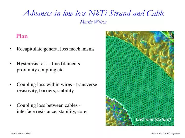
Advances in low loss NbTi Strand and Cable Martin Wilson. Plan Recapitulate general loss mechanisms Hysteresis loss - fine filaments proximity coupling etc Coupling loss within wires - transverse resistivity, barriers, stability

E N D
Advances in low loss NbTi Strand and CableMartin Wilson • Plan • Recapitulate general loss mechanisms • Hysteresis loss - fine filaments proximity coupling etc • Coupling loss within wires - transverse resistivity, barriers, stability • Coupling loss between cables - interface resistance, stability, cores LHC wire (Oxford)
AC loss general • work done to change the field energy • around a closed loop, energy dissipated in a magnetic material • away from end points, loss power • superconductor magnetization comes from • - supercurrents hysteresis • - combined supercurrents and resistive currents coupling • - classical eddy currents • with a transport current flowing, the power supply also does work, increasing the loss by a factor Hysteresis fine filaments • for round filaments
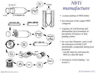
Making fine filaments: resistive transition • resistive transition • depends on processing - 'sausaging' • n always gets worse with finer filaments, so useful J gets less • but intrinsic Jc does not get worse Intermetallics • CuTi intermetallic particles formed during extrusion pre-heat • they don't draw down with the filaments breakage • must surround filament with diffusion barrier - usually Nb
Making fine filaments:Single stacking • single stacking makes the best wire • when packing the extrusion cannister, rods buckle below ~ 1.5mm diameter filament crossover breakage • for a 250mm diameter extrusion cannister, this limits the number of filaments to ~15,000 • for a 0.85mm diameter wire, 15,000 filaments diameter ~ 4.5mm wire 3N7 by European Advanced Superconductors
Making fine filaments: Double stacking • double stacking is easier and allows a large number of filaments • but the filaments are more distorted wire 2A212 by European Advanced Superconductors
Fine filaments: distortion • measure magnetization extrapolated to zero B` and Jc via transport current (measure at high field to minimize self field) • calculate ratio EAS 3N7: r = 0.94 Oxford RHIC: r = 0.92 EAS 2A212: r = 1.40 EAS G2001T6: r = 1.10 IGC SSC B944-2 (CuMn around filaments) r = 1.23 EAS K2001T4: r = 1.15 wire 2A212 by European Advanced Superconductors
Fine filament distortion: why is r <1? • transport current determined by narrowest paths • magnetization current fills up the rest • so should be > 1 data from Lee & Larbalestier bare filament • butJct is measured with a certain electric field - usually 10 -14Wm • Jcmag is measured with zero electric field • even bare filaments have an 'n' value • estimate the decay of magnetization currents • for n = 100 and a 6 mm filament, after 100 sec, Jcmag will have decayed to 88% of its 10 -14Wm value good composites bad composites
Fine filaments: proximity coupling • magnetization reduces with filament diameter down to a point - then it increases • effect is strongest at low field data from Arup Ghosh • expected linear decrease is restored when filaments are etched • enhancement of magnetization is ~ (twist pitch)-1 data from Andries den Ouden
Fine filaments: proximity coupling • experimental data on etching suggests that the effect is caused by supercurrents crossing the matrix • linear dependence on twist pitch suggests these currents have a Jc • Ghosh finds that transverse current density is given by where s is the separation between the filaments and k depends on field and temperature • for minimum sausaging and optimum wire yield, must have s/d ~ 0.15, where s is space between filaments and d is filament diameter - so 3mm filaments 0.45mm separation • Collings finds that transverse currents are suppressed by ferromagnetic additions to the matrix metal - 0.5% Mn in copper works well • adding Si to copper also suppresses proximity currents and also reduces CuTi formation during extrusion • Sumption found that a wire made by (low temperature) hydrostatic extrusion without Nb diffusion barriers had no proximity coupling down to 2mm filament diameter - perhaps the Nb barriers help to launch Cooper pairs across the copper
It Bself Bself J Fine filaments: how many? • self field, due to transport current penetrates from the outside of the wire • Jcin outer filaments nothing inside • twisting makes no difference • penetration produces self field losss (per ramp) where i - It / Ic • when the self field loss becomes comparable with the hysteresis loss within the filaments, there is little to be gained from further subdivision • for example, a 0.8mm diameter wire with 105 filaments of 2mm diameter will have Qs / Qh ~ 50% when ramped from 1T to 6T with i = 0.7
Eddy current coupling between filaments in wires • currents flow along filament and across matrix parallel to field • induced magnetization • current decay time • loss power where p = twist pitch and retis the effective transverse resistivity across the matrix • general formulation in terms of multiple time constants* *Duchateau, Turck and Ciazynski: Handbook on Applied Superconductivity B4.3
w a J J eddy currents Effective transverse resistivity • Two main types of current path poor contact good contact • add reciprocal resistances • or add time constants • (Duchateau et al treatment is more exact)
Matrix resistance 1) Magnetoresistance • lots of good data from Fickett • all for perpendicular B • but it's all we have - fitted by 2) Size effect • separation of filaments is comparable with electron mean free path increase in resistivity to rs where l is the electro mean free path; for copper • example: for RRR= 150 and an inter-filament spacing of 1mm, the resistivity of copper between filaments is increased by a factor 6.7
Calculated and measured ret • RHIC wire with 6mm filaments and 13mm twist pitch • theory of Duchateau fits better because it includes the central island • good or poor contact? - measure it!
Another example • IGC B944-02-20: wire diameter 0.65mm, filament diameter 2.6mm • model as 'macro-filaments, bad contact applies because there is no superconducting path across macro filaments • ref increased by only a factor ~ 3, although rCuMn = 25010-10 Wm ~ 60 the local copper clusters of filaments surrounded by Cu-0.6wt%Mn, all in a sea of copper
A J l qc qo Constraints on increasing ret • use resistive alloy in the matrix • but conflict with stability (early experiments on training) • take minimum quench energy MQEas a criterion of stability Crude model for MQE (all parameters averaged over the cross section) computed MQE for 0.85mm diameter wire in 6T carrying 50% Ic, matrix ratio 1.8:1, 30% of perimeter cooled with boiling helium (using Wiedemann Franz Law Lo = Lorentz number) Conclude: need matrix with a resistivity which is low in longitudinal and high in transverse directions - anisotropic material
Anisotropic r: the physicist's idea • good blocking of currents across filament clusters and around the jacket • problem: they couldn't make it!
Anisotropic r: the wire maker's idea • barrier round each filament, immerse in a sea of copper • good mechanical properties for drawing • problem:only change rt from goodto bad contact • problem: conduction round the outer jacket idea 2 • resistive material throughout the core • thick barrier between core and jacket • copper jacket • low losses • problem: stability - the copper is too far from the filaments
Jt q Stability: do filaments see the copper? • MQE analysis assumes that the NbTi are intimately mixed - how intimate? • over long lengths the electric field in NbTi and copper are the same • what about the temperature? - uniform over Cu but not NbTi • define a characteristic distance where k = thermal conductivity of NbTi, qs = current sharing temperature, Jt = transport current density in NbTi, l = local filling factor, r = copper resistivity, a = filament radius • solve for power generation as a function of copper temperature qn • for acceptable behaviour choose a2/d2 < 4, ie dfil < 4d • for NbTi in Cu at 6T d ~ 10mm • so require dfil < 40mm • a mixture of NbTi and CnMn typically has k ~ 10 kNbTi • so macro filament diameter can be ~ 120mm
Ideas for future wires (1) • barriers more efficient in blocking crossing current • still respect the dynamic stability condition • CuMn next to filament to suppress proximity coupling gain a factor 2½
Ideas for future wires (2) - a better idea* • clusters of filament in CuMn • copper islands inside clusters of filaments • bundles of clusters inside copper *by G Volpini and Luvata Fornaci di Barga • it may help to add a resistive barrier around bundles • could gain a factor up to ~ 4 in ret over idea (1)
I Bs Cables: style of design • wires must be fully transposed against self field braid • rope: AC3 • braid: MOBY and early RHIC • Rutherford: AC5 and Tevatron rope Rutherford • Rutherford probably won because it can be compacted to high density and tolerance
Ra Rc Cable coupling patterns crossover resistance Rc adjacent resistance Ra 1) Field transverse: coupling via crossover resistance Rc 3) Field parallel: coupling via adjacent resistance Ra 2) Field transverse: coupling via adjacent resistance Ra
B` 2b 2c Coupling magnetization in cables • Field transverse • coupling via crossover resistance Rc where M = magnetization per unit volume of cable, p twist pitch, N = number of strands rc and ra are resistance * unit area of contact, Rc and Ra are resistance per contact • Field transverse • coupling via adjacent resistance Ra where q = slope angle of wires Cosq~ 1 • Field parallel • coupling via adjacent resistance Ra (usually negligible) • Field transverse • ratio crossover/adjacent So without increasing loss too much can make Ra much less than Rc - anisotropy
Ra and Rc • we can increase (and reduce losses) RaandRcby surface coatings and creative chemistry • but do we want them to be too large? • worries about stability and current sharing • memories of MOBY and Rutherford quadrupole, type A/B behaviour in SSC booster dipoles • suggest we should make RaandRcas large as necessary to limit the loss - but no larger • because the loss is anisotropic, it pays to make RaandRcanisotropic • data from David Richter CERN • cored cable, make Rc~ 40 Ra • lower losses with good stability
Measuring rc when it's >> ra Usually, only a tiny fraction of current goes through the core, making it difficult to measure rc in an intact cable. Two methods of forcing current through the core: a) cut off the cable edges measure resistance between the faces b) remove two wires measure resistance between the remaining 2 groups of wires • Typical numbers • for stainless core foil find Rc ~ 10mW • for FAIR target Ra ~ 200mW idea from David Richter
Ra < 1mW (soldered) Ra = 60 - 70mW Ra = 600 - 700mW Ra = 8 - 9 mW Measuring cable stability • use carbon paste heaters to inject short energy pulses to individual strands • measure the MQE • it looks like low Ra is best • but how much does it really tell us about magnet stability? measurements courtesy of Gerard Willering
Low loss NbTi Strand & Cable: concluding remarks • Hysteresis Loss • usually dominant many very fine filaments (but not too many or self field loss) • filament distortion: - longitudinal low n - transverse enhanced magnetization • intermetallics: - diffusion barriers or low temperature extrusion • stacking: - single stack best properties - double stack more filaments • proximity coupling: - ferromagnetic additions to copper CuMn - or no diffusion barrier Coupling between filaments • anisotropic matrix resistance - high transverse low loss, - low longitudinal stability • MQE gives estimate of stability - critical distance for intimate mixing of NbTi and Cu • new ideas needed for higher transverse resistance without loosing stability Cables • the high interface resistance needed to control losses high ramp rate may prejudice stability - surface coatings Ra > Rc , - core Ra << Rc low loss without losing stability NbTi • now into middle age, NbTi still offers substantial advantages for pulsed use: • - the finest filaments, low filament distortion, • - precise fine structures of resistive alloy and copper in the matrix with no mixing • - ductility