Download
1 / 78
780 likes | 878 Vues
RIT Senior Design Project 10662 D3 Engineering Camera Platform . Friday November 6, 2009 9:00am to 11:00am. Team Members . Gregory Hintz (EE) Project Manager Samuel Skalicky (CE) Lead Engineer, FPGA Board Jeremy Greene (EE) Connector Board Jared Burdick (EE) Power

E N D
RIT Senior Design Project 10662D3 Engineering Camera Platform Friday November 6, 2009 9:00am to 11:00am
Team Members • Gregory Hintz (EE) • Project Manager • Samuel Skalicky (CE) • Lead Engineer, FPGA Board • Jeremy Greene (EE) • Connector Board • Jared Burdick (EE) • Power • Michelle Bard (ME) • Environmental • Tony Perrone (ME) • Physical Design
Advisors • Scott Reardon (D3 Engineering) • Kevin Kearney (D3 Engineering) • Dr. Robert Kremens (RIT-Imaging Science) • Philip Bryan (RIT – Industry Guide)
Project Status • Risks • BOM • Analysis • Feasibility • Designs • Test Plans
Schedule for the Design Review • Overview • Gregory Hintz • Electrical Discussion • Processor Board and FPGA • Samuel Skalicky • Connector Board, INS System • Jeremy Greene • Mechanical Discussion • System Design • Tony Perrone • Environmental Concerns • Michelle Bard
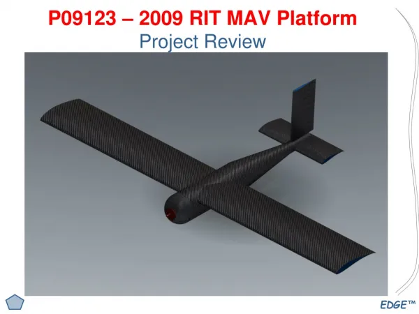
What is the Customer Looking for? Integrate supplied components Ruggedized Unit Flight-capable package Can record and transmit Capable of processing
Supplied Components Customer Needs Met External INS units Data processing (overlay) Real time viewing Store full-res. Data during flight Support NovAtel GNSS board • Integrate supplied components • 10MP Visual Band Camera • 1.3MP IR Camera • Spatial Sensors • NovAtel OEM Board OEMV3 • NovAtel OEM Board OEMV2 • Camera Processing Board • Capture data from two cameras • Capture 10MP @ 1fps • Capture 1.3MP @ 30fps • Capture INS data @ 30/sec (simultaneously)
Camera Components Customer Needs Met External INS units Data processing (overlay) Real time viewing Store full-res. Data during flight Support NovAtel GNSS board • Integrate supplied components • 10MP Visual Band Camera • 1.3MP IR Camera • Spatial Sensors • NovAtel OEM Board OEMV3 • NovAtel OEM Board OEMV2 • Camera Processing Board • Capture data from two cameras • Capture 10MP @ 1fps • Capture 1.3MP @ 30fps • Capture INS data @ 30/sec (simultaneously)
Camera Components Customer Needs Met External INS units Data processing (overlay) Real time viewing Store full-res. Data during flight Support NovAtel GNSS board • Integrate supplied components • 10MP Visual Band Camera • 1.3MP IR Camera • Spatial Sensors • NovAtel OEM Board OEMV3 • NovAtel OEM Board OEMV2 • Camera Processing Board • Capture data from two cameras • Capture 10MP @ 1fps • Capture 1.3MP @ 30fps • Capture INS data @ 30/sec (simultaneously)
Spatial Sensing Customer Needs Met External INS units Data processing (overlay) Real time viewing Store full-res. Data during flight Support NovAtel GNSS board • Integrate supplied components • 10MP Visual Band Camera • 1.3MP IR Camera • Spatial Sensors • NovAtel OEM Board OEMV3 • NovAtel OEM Board OEMV2 • Camera Processing Board • Capture data from two cameras • Capture 10MP @ 1fps • Capture 1.3MP @ 30fps • Capture INS data @ 30/sec (simultaneously)
Output INS data format # of shot, (FLIGHT INFORMATION, Pitch, ect….) 675,495060.000000,39.377116,-82.774721,1442.237213,177.966706,-6.573488,87.156026 676,495063.000000,39.375698,-82.773364,1437.212509,178.655193,-2.978762,89.591399 677,495066.000000,39.374288,-82.771967,1432.054779,177.896426,-3.434334,92.544970 678,495069.000000,39.372892,-82.770509,1428.557648,177.391126,-12.302477,92.517868 679,495072.000000,39.371514,-82.768882,1425.166306,178.138512,-9.035039,88.154010 680,495075.000000,39.370128,-82.767133,1425.035141,176.875920,-1.502685,89.783104 681,495078.000000,39.368761,-82.765407,1424.326828,176.056416,-6.737449,90.066296 682,495081.000000,39.367471,-82.763622,1421.768311,175.569431,-7.973052,88.809422 683,495084.000000,39.366537,-82.761748,1427.402252,176.045872,-7.985133,86.404080
Processing elements Customer Needs Met External INS units Data processing (overlay) Real time viewing Store full-res. Data during flight Support NovAtel GNSS board • Integrate supplied components • 10MP Visual Band Camera • 1.3MP IR Camera • Spatial Sensors • NovAtel OEM Board OEMV3 • NovAtel OEM Board OEMV2 • Camera Processing Board • Capture data from two cameras • Capture 10MP @ 1fps • Capture 1.3MP @ 30fps • Capture INS data @ 30/sec (simultaneously)
OEM Digital Signal Processing Board Signal Processing already done on Customer Supplied Interface. Image overlay Compression Resolution of Images Outputs 10/100 Ethernet S-Video Software interface available
Processing elements Customer Needs Met External INS units Data processing (overlay) Real time viewing Store full-res. Data during flight Support NovAtel GNSS board • Integrate supplied components • 10MP Visual Band Camera • 1.3MP IR Camera • Spatial Sensors • Camera Processing Board • Capture data from two cameras • Capture 10MP @ 1fps • Capture 1.3MP @ 30fps • Capture INS data @ 30/sec (simultaneously)
Processing Elements DSP • Energy Efficient • Single Pipeline • Easy Implementation • Math based ISA FPGA • Inputs/Outputs • Flexible Architecture • Faster Speed • Parallel Processing
DSP • Customer programmable • Encoding/Decoding media • Peripherals • Role in this design • Image compression • Real time streaming of data • INS interface • Required skills • Implementable Knowledge of C • DSP/BIOS
FPGA • FPGA Selection • Quicker time to fabrication • Supreme configurability/Field reprogrammable • Has the I/O needed • Parallel processing
FPGA • Xilinx Selection • Resources available to the team • Larger range of choices than other companies • Customer preference • Model XC6SLX75T Selection • Package size (23mm x 23mm) • High speed transceiver count • I/O pin count • Cost effectiveness
Data Flow – Initial Design • Pictures • Camera FPGA OEM • INS Data • INS OEM
Data Flow – Final Design • Pictures • Camera FPGA OEM • Camera FPGA HD • INS Data • INS OEM FPGA HD
Data Speeds • Image • IR: 30 images / second • VGA=640x480 • 9.2 MHz • Visible :1 image / second • 10.7MP=3664x2748 • 10.07 MHz • INS • 30 captures / second • 1kB=8kb • 8000 baud **Note: baud = bits per second (RS-232)
FPGA Pin Speeds • Minimum values • 13ns -> 76 MHz • 5ns -> 200 MHz
External Interfaces andthe Connector Board 2x GigE 2x Camera Link 10/100 Ethernet Power Supply External INS Connector Board D3 OEM Board
External Interfaces andthe Connector Board Power Supply External INS 2x Camera Link 2x GigE RCA output 10/100 Ethernet USB port Connector Panel
External Interfaces andthe Connector Board • Goal: • All interfaces routed through and mounted on the Connector Board • Reality: • Various different mountings and routings necessary
Interface Routing andConnector Mounting 2x Camera Link External INS Power Supply • 2x Camera Link = nearly full width of Connector Board Connector Panel
Interface Routing andConnector Mounting • GigE mounted on FPGA Board 2x GigE FPGA Board (bottom view) Connector Panel
Interface Routing andConnector Mounting RCA 10/100 Ethernet • RCA and 10/100 Ethernet routed directly to D3 OEM Board 10/100 Ethernet RCA output D3 OEM Board (top view) Connector Panel
Interface Routing andConnector Mounting USB port • USB routed directly to internal GNSS receiver Connector Panel
The Connector Board • Having determined what it needs to do, design could commence Customer Provided Block Diagram