Download
1 / 36
370 likes | 613 Vues
EENG 449b/CPSC 439b Computer Systems Lecture 7 ARM Assembly Programming and SOS. Feb 2, 2005 Prof. Andreas Savvides Spring 2005 http://www.eng.yale.edu/courses/2005s/eeng449b. Announcements. Programming assignment 1 out today We will discuss it in class Starting code

E N D
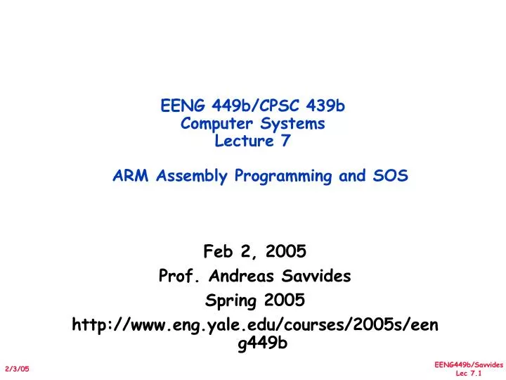
EENG 449b/CPSC 439b Computer SystemsLecture 7 ARM Assembly Programming and SOS Feb 2, 2005 Prof. Andreas Savvides Spring 2005 http://www.eng.yale.edu/courses/2005s/eeng449b
Announcements • Programming assignment 1 out today • We will discuss it in class • Starting code • Paper presentations • 1: SOS & SOS programming • Simulators: ATEMU, AURORA and TOSSIM
Some Definitions • ADR – assembler pseudo instruction • Assembled into an ADD or SUB instruction • EQU • LDRB – load register byte LDRB r0,[r1] LDRB r0,[r1], #1 ; immediate value indexes into the array • &0a – new line, &0d – carriage return • SWI – Software Interrupt – puts the processor in supervisor mode and starts executing instructions from address 0x08
Branch Instructions Some of these are decided with the help of the program status register
Stacks and Subroutines LDMIA - Load Multiple Increment After
Update Base Address Register with Load/Store Multiple Instructions
Implementing a STACK Note that this does not exist in the ARM architecture we will implement it!
Relationship between the two different views of LDM/STM instructions
Programming Assignment • Let’s look into the programming assignment requirements • Discussion items • Node architecture • UART setup inside the OKI processor • Connecting to the JTAG and Seehau • Burning your code in FLASH • Stepping through your code & resetting • Starting code for this assignment
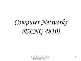
Sensor node created for experimentation Low cost, low power, many peripherals Integrated accelerometer, light and temperature sensor Part of a EENG449b project last semester Uses an IEEE 802.15.4 protocol Chipcon 2420 radio OKI ARM Thumb Processor 256KB FLASH, 32KB RAM Max clock speed 58MHz, scales down to 2MHz Multiple power management functions Powered with 3AA batteries & has external connectors for attaching peripheral boards Designed at Yale Enalab and Cogent computer systems, will be used as the main platform for the course Lab PlatformXYZ Sensor Node
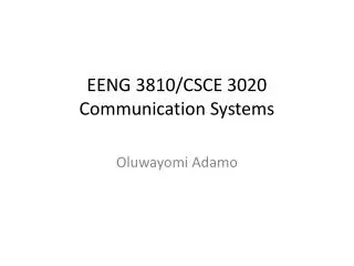
Voltage Regulator RTC DS1337 OKI μC I2C 3 x AA batteries XYZ: Supervisor Circuitry & Low Power Sleep 2.5V 3.3V Enable Interrupt (SQW) WAKEUP • Step 1: The μC selects the total time that wants to be turned off and programs the DS1337 accordingly, through the 2-wire serial interface. • Step 2: The DS1337 turns-off the μC and uses its own crystal to keep the notion of time. • Step 3: The DS1337 wakes up the μC after the programmed amount of time has elapsed. • Note that the DS1337 RTC can disable the voltage regulator and completely turn-off the sensor node! • In sleep mode, the whole device will consume around 60uW of power DS1337 Real Time clock datasheet: http://pdfserv.maxim-ic.com/en/ds/DS1337.pdf
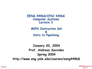
Light Accelerometer OKI μC Temperature XYZ: On Board Sensors AIN0 A D C AIN1 X AIN2 Y PIOE5(EXINT0) Light Sensor datasheet (TSL251R): http://www.goblack.de/desy/digitalt/sensoren/tsl-250/tsl250r.pdf Temperature Sensor datasheet (TMP05): http://www.analog.com/UploadedFiles/Data_Sheets/192632828TMP05_6_prk.pdf 2-axis accelerometer datasheet (ADXL202E): http://www.rotomotion.com/datasheets/ADXL202E_a.pdf
OKI ARM ML675001/67Q5002/67Q5003 ARM7TDMI
External SRAM starts here Internal RAM starts here FLASH Starts here
Demo Example Using the JTAG Interface • Hardware you need: • OKI L67Q4004 CPU board • Serial Cable • 5V power supply • Optional: Seehau JTAG pod – only 2 available so you will need special arrangement to use this • Software you need • Optional: Seehau debugger installed in CO-40 • Arm-gnu tools – installed in CO-40 • You can also install them on your own PC but you will not have access to the Seehau Debugger! • Visit the XYZ website http://www.eng.yale.edu/enalab/XYZ to get the tools
A Sample Makefile CFLAGS = -Wall -g -nostartfiles -mthumb-interwork -marm INCLUDE = -Iinc/ -Isrc/ OBJS = define.o common.o init.o irq.o pio_sample.o reentrant_irq.o LDFLAGS = -Wl,-Tarm.ld all: PIO.elf PIO.elf: $(OBJS) arm-elf-gcc $(CFLAGS) $(LDFLAGS) $(OBJS) $(LIBS) -o PIO.elf %.o: inc/%.s arm-elf-gcc -c $(INCLUDE) $(CFLAGS) $< %.o: src/%.c arm-elf-gcc -c $(INCLUDE) $(CFLAGS) $< %.o: src/%.s arm-elf-gcc -c $(INCLUDE) $(CFLAGS) $< %.bin: % arm-elf-objcopy -O binary $<.elf $@ clean: rm -f *.o PIO.elf PIO.hex hex: arm-elf-objcopy -I elf32-little -O ihex PIO.elf PIO.hex
The Linking Process • After compiling the code, you need to link it. • The linker script will specify the location in memory where your code will reside • The start of the linker file looks like this: MEMORY { rom (rx) : ORIGIN = 0x00000000, LENGTH = 256K ram (rx) : ORIGIN = 0x50000000, LENGTH = 32K } /* section definition */ SECTIONS { …..
Application Development Cycle(Demo) Code Development Linker determines Memory mapping (see arm.ld) Compile & Link File output format Can be elf, bin, hex Upload Code to Chip .elf for JTAG Or .hex for serial port Run/Debug
Compiling your code To compile the code you simple run the makefile • $ make • The default output is a .elf file • You can use this with Nohau Seehau debugger BUT cannot be used with the OKI programming utility • To use the programming utilit you need to convert your file to intel hex format. • arm-elf-objcopy -I elf32-little -O ihex PIO.elf PIO.hex • Or type make hex in the sample Makefile
An Example Program for the OKI ARM PIO Program Posted on the website: Files in the inc directory: common.h - definitions specific to the board define.s - assembler common definitions – don’t need to change this irq.h - header files for interrupt functions – no change ml674000.h – include file for the OKI chip that lists the locations of registers – may need to change this for the 674Q4003 device
An Example Program for the OKI ARM PIO Program Posted on the website: init.s - chip initialization file. This initializes the exception table and interrupt handling mechanism – don’t need to change this reentrant_irq.s – interrupt handling mechanisms – don’t need to change this Files in the src directory: pio_sample.c - this is where the main() function. It is the entry point for any application. Pay attention to the initializations !!!