Download
1 / 31
380 likes | 621 Vues
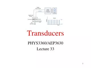
Transducers. Presented By : Er.Abinash Singh Ph.D Scholar Deptt . Of Electrical Engg . Introduction.

E N D
Transducers Presented By: Er.Abinash Singh Ph.D Scholar Deptt. Of Electrical Engg.
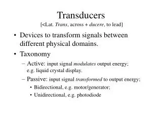
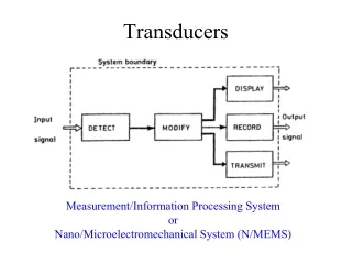
Introduction • A transducer can be defined as a device capable of converting energy from one form into another. Transducers can be found both at the input as well as at the output stage of a measuring system. • The input transducer is called the sensor, because it senses the desired physical quantity and converts it into another energy form. • The output transducer is called the actuator, because it converts the energy into a form to which another independent system can react, whether it is a biological system or a technical system.
Contd… • A transducer is a device that converts one type of energy to another. The conversion can be to/from electrical, electro-mechanical, electromagnetic, photonic, photovoltaic, or any other form of energy. While the term transducer commonly implies use as a sensor/detector, any device which converts energy can be considered a transducer.
Classification of Transducers • The transducers may be classified on basis of electrical principles involved, methods of application, methods of energy conversion used, nature of output signal etc. • a) Primary and secondary transducers. • b) Active and passive transducers • c) Analog and digital transducers • d) Transducers and inverse transducers.
Resistive Transducers • In such a transducer, the resistance between the output terminals of a transducer gets varied according to the measurand. • Resistive transducers are preferred over the other transducers because dc and ac both are suitable for resistance measurement. • Examples: Potentiometer, Strain gauge, Thermistor, Thermocouple.
Potentiometer • A position or displacement transducer may be built with a linear or rotary potentiometer or a pot for short. It follows that the resistance linearly relates to the wire length. Thus, by making an object to control the length of the wire, as it is done in a pot, a displacement measurement can be performed. • Because a resistance measurement requires passage of an electric current through the pot wire, the potentiometric transducer is of a passive type; that is, it requires an excitation signal, (e.g., dc current). • It converts linear or rotational displacement into a voltage.
Contd… • The voltage across the wiper of a linear pot is proportional to the displacement d: • where D is the full-scale displacement and E is the voltage across the pot (excitation signal). The force which is required to move the wiper comes from the measured object, and the resulting energy is dissipated in the form of heat. When the motion of wiper are translational as well as rotational, the potentiometer is called helipot
Contd… • Types of Potentiometers: • Wire wound potentiometers • Carbon film potentiometer • Thin film Potentiometer • Hot moulded Carbon potentiometer • Cermet potentiometer(In this, the resistance element is made of ceramic base)
Contd… • Merits: • They are cheap, easy to operate, simple in construction and very useful for simple applications • They have very good frequency response except for the wire wound type. • They can measure large amplitude of displacement. • They have high electrical efficiency. • Demerits: • The main drawback is the wear and tear caused of wiper and its effect on the life of transducer. • They require large force for wiper movement • The output is insensitive to variation in displacement of wiper b/w two consecutive turns of pot.
Strain Gauge • A strain gauge is a device used to measure the strain of an object. A strain gauge is a resistive elastic sensor whose resistance is a function of applied strain (unit deformation). • Because all materials resist deformation, some force must be applied to cause deformation. Hence, resistance can be related to applied force. That relationship is generally called the piezoresistive effect
Contd… • A strain gauge takes advantage of the physical property of electrical conductance and its dependence on the conductor's geometry. When an electrical conductor is stretched within the limits of its elasticity such that it does not break or permanently deform, it will become narrower and longer, changes that increase its electrical resistance end-to-end. • Conversely, when a conductor is compressed such that it does not buckle, it will broaden and shorten, changes that decrease its electrical resistance end-to-end. From the measured electrical resistance of the strain gauge, the amount of applied stress may be inferred.
Contd… • Types of strain gauge • Wire strain gauge • Thin film strain gauge • Foil strain gauge • Semiconductor strain gauge • (Learn the derivation from class notes.)
Contd… • Merits: • They permit the measurement of very small strain i.e as small as 0.01 micron • The semiconductor strain gauges can be manufactured in very small sizes ranging from 0.7 to 7 mm. • They have got frequency response upto 1012 Hz. • They are almost free from hysteresis effect • Their fatigue life is much higher. • Demerits: • They are expensive brittle and highly sensitive to temperature variations
Thermistor • A thermistor is a resistor whose value varies with temperature. the thermistor is also a resistive device that changes its resistance predictably with temperature. Its benefit is a very large change in resistance per degree change in temperature, allowing very sensitive measurements over narrow spans. Due to its very large resistance, lead wire errors are not significant. However, there are several disadvantages to the thermistor: 1. It is a very nonlinear device and reasonable accuracy is obtained only over narrow spans (see Figure). 2. It is quite small and will exhibit errors due to self heating. 3. Exposure to high temperature will cause a dramatic and permanent shift in its output characteristics. • Most applications of the thermistor are in commercial and laboratory applications. Few are used in industrial process control.
Contd… • Commercial forms of thermistors: a)Bead type b)Disc Type c)Rod Type d)Probe type e)Washer Type
Thermocouple • A thermocouple consists of two pieces of dissimilar metals with their ends joined together (by twisting, soldering or welding). When heat is applied to the junction, a voltage, in the range of milli-volts (mV), is generated. A thermocouple is therefore said to be self-powered.
Contd… Principle of operation In 1821, the German–Estonian physicist Thomas Johann Seebeck discovered that when any conductor is subjected to a thermal gradient, it will generate a voltage. This is now known as the thermoelectric effect or Seebeck effect. Any attempt to measure this voltage necessarily involves connecting another conductor to the "hot" end. This additional conductor will then also experience the temperature gradient, and develop a voltage of its own which will oppose the original. Fortunately, the magnitude of the effect depends on the metal in use. Using a dissimilar metal to complete the circuit creates a circuit in which the two legs generate different voltages, leaving a small difference in voltage available for measurement. That difference increases with temperature, and is between 1 and 70 microvolts per degree Celsius (µV/°C) for standard metal combinations. The voltage is not generated at the junction of the two metals of the thermocouple but rather along that portion of the length of the two dissimilar metals that is subjected to a temperature gradient. Because both lengths of dissimilar metals experience the same temperature gradient, the end result is a measurement of the temperature at the thermocouple junction.
Contd… • Advantages: • Thermocouples are used on most transformers. The hot junction is inside the transformer oil and the cold junction at the meter mounted on the outside. With this simple and rugged installation, the meter directly reads the temperature rise of oil above the ambient temperature of the location. • In general, thermocouples are used exclusively around the turbine hall because of their rugged construction and low cost. • A thermocouple is capable of measuring a wider temperature range • Disadvantages: • If the thermocouple is located some distance away from the measuring device, expensive extension grade thermocouple wires or compensating cables have to be used. • Thermocouples are not used in areas where high radiation fields are present (for example, in the reactor vault). Radioactive radiation (e.g., Beta radiation from neutron activation), will induce a voltage in the thermocouple wires. Since the signal from thermocouple is also a voltage, the induced voltage will cause an error in the temperature transmitter output. • Thermocouples are slower in response • If the control logic is remotely located and temperature transmitters (milli-volt to milli- amp transducers) are used, a power supply failure will of course cause faulty readings.
Inductive Transducers • These can be classified as: • Linear variable differential transformer • Inductive transducer utilising change in self-inductance • Variable Reluctance inductive transducer • Inductive transducer working on the principle of variation of mutual inductance • Eddy current Sensors
LVDT • Linear variable differential transformer(LVDT) • A linear variable differential transformer (LVDT),which can also be called a mutual-inductance element, that operates on the inductance ratio principle. Here three coils are wound onto the same insulating tube containing the high-permeability iron core. Alternating current is applied to the primary coil (P) in the center, and if the core is in the center, equal voltages are induced in the secondary coils (#1 and #2) by the magnetic flux. Usually the secondary coils are wired in series, and therefore when the core is centered, the resulting output is zero. As the core moves to the left or right, the voltage induced in coil #1 or #2 will predominate. • The LVDT-type transducers are also available in therotary form and can be obtained with ranges from 0–30 to 0–10,000 PSIG (0–210 kPa to 0–70 MPa). Their limitations include mechanical wear and vibration sensitivity.
Contd… The Linear Variable Differential Transformer (LVDT) is a type of electrical transformer used for measuring linear (i.e. translational) displacement. A counterpart to this device that is used for measuring rotary displacement is called a Rotary Variable Differential Transformer (RVDT). The linear variable differential transformer has three solenoidal coils placed end-to-end around a tube. The center coil is the primary, and the two outer coils are the secondaries. A cylindrical ferromagnetic core, attached to the object whose position is to be measured, slides along the axis of the tube. An alternating current is driven through the primary, causing a voltage to be induced in each secondary proportional to its mutual inductance with the primary. The frequency is usually in the range 1 to 10 kHz. As the core moves, these mutual inductances change, causing the voltages induced in the secondaries to change. The coils are connected in reverse series, so that the output voltage is the difference (hence "differential") between the two secondary voltages.
Contd… Advantages of the LVDT are: Disadvantages of LVDT are: Sometimes the transducer performance is affected by the vibrations. The receiving instrument must be selected on ac signals or a demodulator must be used if a dc output is required. Relatively large displacements are required for appreciable differential output. These devices are sensitive to stray magnetic fields but its problem is overcome by using magnetic shields. • The sensor is a non contact device with no or very little friction resistance with small resistive forces; • Hysteresis (magnetic and mechanical) are negligible; • Output impedance is very low; • There is low susceptibility to noise and interferences; • Its construction is solid and robust, • Infinitesimal resolution is possible.
OPTICAL TRANSDUCERS The movement of elastic pressure sensors can also be used to operate optical sensors. As the process pressure moves a diaphragm sensor, which in turn lifts a vane in front of an infrared light beam, the amount of light impinging on the measuring diode 2 varies (Figure). A reference diode is also provided to compensate for the aging of the light source (LED) or for dirt buildup on the optics. This transducer is insensitive to temperature variations, as such variations affect the measuring and reference diodes in the same way. Because the amount of movement in the sensor is very small (0.5 mm), both the hysteresis and the repeatability errors are negligible.
Infrared Detectors • In general, IR detectors are good for detecting hydrocarbon based fires (i.e., fires that have strong IR emissions). IR detectors are generally not as fast as UV detectors to respond to a fire. • A disadvantage of IR is that ice buildup can desensitize the detector (lessen its ability to detect a fire), but this can be overcome with heated optics. IR does not respond to electric arc welding unless the welding is very close to the detector, in which case the detector may alarm due to seeing the burning from the welding process. • Some IR detectors have flicker and statistical analysis algorithms to minimize the effects of black body sources, a false alarm source.
Ultrasonic Sensors • For noncontact distance measurements, an active sensor which transmits some kind of a pilot signal and receives a reflected signal can be designed. The transmitted energy may be in the form of any radiation—for instance, electromagnetic in the optical range electromagnetic in the microwave range, acoustic, and so forth. Transmission and reception of the ultrasonic energy is a basis for very popular ultrasonic-range meters, and velocity detectors. • Ultrasonic waves are mechanical acoustic waves covering the frequency range well beyond the capabilities of human ears (i.e., over 20 kHz). However, these frequencies may be quite perceptive by smaller animals, like dogs, cats, rodents, and insects. Indeed, the ultrasonic detectors are the biological ranging devices for bats and dolphins. • When the waves are incident on an object, part of their energy is reflected. In many practical cases, the ultrasonic energy is reflected in a diffusemanner; that is, regardless of the direction from which the energy comes, it is reflected almost uniformly within a wide solid angle, which may approach 180◦. If an object moves, the frequency of the reflected waves will differ from the transmitted waves. This is called the Doppler effect. • The distanceL0 to the object can be calculated through the speed v of the ultrasonic waves in the media, and the angle
Capacitive transducers • Capacitive sensors are more often used for linear than angular proximity measurements. Either the dielectric or one of the capacitor plates is movable for displacement measurement. Capacitive proximity sensors use the measured object as one plate, and the sensor contains the other plate. The capacitance changes according to the question. where k = is a constant, depending on the area of the plates and the dielectric constant d = the distance between the plates • Capacitive transducers are available with packaged signal-conversion circuitry for DC output operation. Capacitive sensors are widely used for dimensional inspections in large-volume manufacturing operations, such as the filling of containers or the monitoring of the wearing of moving surfaces. The capacitive displacement sensors have very broad applications, they are employed directly to gauge displacement and position and also as building blocks in other sensors where displacements are produced by force, pressure, temperature, and so forth.
Contd… The proximity switches illustrated in Figure can detect liquids, glass, plastic, wood, or metallic objects. For the proximity switches shown, the sensing distance can be fixed or adjustable between 0.1 and 1.0 in. (3 to 25 mm). Proximity switches provided with sensing plates can operate over a range of 0.2 to 5 in. (5 to 127 mm), can detect capacitance changes down to 0.02 pF, and can detect more than 100 operations/s. The switch is operated when the capacitance caused by the approaching object exceeds the reference level set to trigger the switch. Types of Capacitive transducers( on basis of the method of variation of pressure): C=εA/d By varying the overlapping area of plates(A) By varying the distance between the plates(d) By varying the relative permittivity of dielectric material between the two plates.
Piezoelectric Sensors • The piezoelectric sensor is a self-generating device that is • ideal for the measurement of such dynamic events as shock • and vibration. They are basically motion transducers with • large output signals and comparatively small sizes. They are • available with very high natural frequencies and are suitable • for high-frequency applications and shock measurements. • Their sensing element is sandwiched between the transducer • body and a seismic mass (usually tungsten). Because the • seismic mass is constant, the force acting on the sensing • element (F = ma) is proportional to acceleration. If the sens- • ing element is a quartz crystal or lead-zirconate-titanate • (PZT), an electric charge is generated (150 times more for • PZT than for quartz) that is in proportion to the experienced • force and therefore to acceleration.
Contd… These devices utilize a mass in direct contact with the piezoelectric component or crystal. A separation of charge is produced on the opposite faces of the crystal when it is subjected to acceleration forces. The magnitude of the voltage produced is in proportion to mechanical deformation and, hence, acceleration. Piezoelectric crystals are affected in their output by temperature variations; however, quartz and some of the newer piezoelectric ceramics are superior to such ceramics as bar iumtitanate or PZT in their reduced sensitivity to temperature. Two commonly used piezoelectric crystals are PZT and crystalline quartz. They are both self-generating materials and produce a large electric charge for their size. As a result, PZTs are more sensitive and smaller in size than quartz counterparts. These accelerometers are useful for high-frequency applications. Fig. shows impedance characteristics of a piezoelectric transducers
Humidity & Moisture Sensors Humidity refers to the water vapor contained in the air at a particular temperature. Warm air has a greater capacity for water vapor than does cold air. Relative humidity (RH) is the ratio of the actual partial pressure of the water vapor to the saturation vapor pressure at a particular temperature. Fig shows Capacitive Moisture Sensing System A hygrometer is an instrument used for measuring the moisture content in the environmental air, or humidity. Most measurement devices usually rely on measurements of some other quantity such as temperature, pressure, mass or a mechanical or electrical change in a substance as moisture is absorbed. From calculations based on physical principles, or especially by calibration with a reference standard, these measured quantities can lead to a measurement of humidity. Modern electronic devices use temperature of condensation, or changes in electrical capacitance or resistance to measure humidity changes.
Contd… • For applications where cost, space, or fragility are relevant, other types of electronic sensors are used, at the price of a lower accuracy. In capacitive humidity sensors, the effect of humidity on the dielectric constant of a polymer or metal oxide material is measured. With calibration, these sensors have an accuracy of ±2% RH in the range 5–95% RH. Without calibration, the accuracy is 2 to 3 times worse. Capacitive sensors are robust against effects such as condensation and temporary high temperatures. Capacitive sensors are subject to contamination, drift and aging effects, but are suitable for many applications. • In resistive humidity sensors, the change in electrical resistance of a material due to humidity is measured. Typical materials are salts and conductive polymers. Resistive sensors are less sensitive than capacitive sensors - the change in material properties is less, so they require more complex circuitry. The material properties also tend to depend both on humidity and temperature, which means in practice that the sensor must be combined with a temperature sensor. The accuracy and robustness against condensation vary depending on the chosen resistive material. Robust, condensation-resistant sensors exist with an accuracy of up to ±3% RH. • In thermal conductivity humidity sensors, the change in thermal conductivity of air due to humidity is measured. These sensors measure absolute humidity rather than relative humidity