Download

1 / 38
610 likes | 1.68k Vues
DIGITAL TRANSDUCERS. BY RAJASEKHAR REDDY.CH VENKATA AJAY.G VINAY KUMAR.U. Topics. Shaft Encoders Incremental Optical Encoder Absolute Optical Encoder Encoder Error Digital Resolvers Digital Tachometers Hall Effect Sensors Measurement of Translatory Motion Limit Switches.

E N D
DIGITAL TRANSDUCERS BY RAJASEKHAR REDDY.CH VENKATA AJAY.G VINAY KUMAR.U
Topics • Shaft Encoders • Incremental Optical Encoder • Absolute Optical Encoder • Encoder Error • Digital Resolvers • Digital Tachometers • Hall Effect Sensors • Measurement of Translatory Motion • Limit Switches
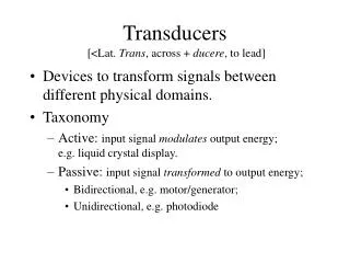
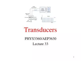
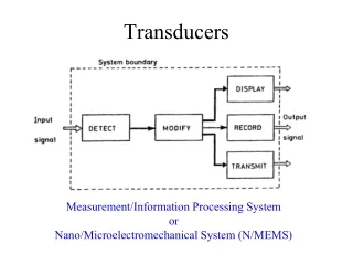
INTRODUCTION • What is a Digital Transducer ? • Any transducer that presents information as discrete samples and that does not introduce a quantization error when the reading is represented in the digital form may be classified as a digital transducer • What is an encoder ? • Any transducer that generates a coded of a measurement can be termed an encoder • SHAFT ENCODERS— They are Digital Transducers that are used for measuring ANGULAR DISPLACEMENTS and ANGULAR VELOCITIES.
Applications Of Shaft Encoders 1.Control of robotics manipulators 2.Machine tools 3.Digital tape-transport mechanisms 4.Servo plotters 5.Printers 6.Satellite mirror positioning system
Encoder Types Shaft encoders can be classified into three categories 1. Incremental Encoders 2. Incremental Optical Encoders 3. Absolute Optical Encoders Incremental Encoders 1.Optical (photosensor) method 2.Sliding contact (Electrical conducting) method 3.Magnetic saturation (Reluctance) method
Optical Encoder (1) • The optical encoder uses an opaque disk that has one or more circular tracks, with some arrangement of identical transparent windows. • A parallel beam of light is projected to all tracks from one side of the disk • The light sensor could be a silicon photodiode, a phototransistor, or a photovoltaic cell. • The light from the source is interrupted by the opaque areas of the track, the output signal from the probe is a series of voltage pulses
Sliding Contact (2) • The transducer disk is made of an electrically insulating material • The conducting regions correspond to the transparent windows on an optical encoder disk • All conducting areas are connected to a common slip ring on a encoder shaft • A constant voltage Vref is applied to the slip ring using a brush mechanism
Incremental Optical Encoder (2) • The disk has a single circular track with identical and equally spaced transparent windows. • The area of the opaque region between adjacent windows is equal to the window area. • Two photodiode sensors (pick offs 1 and 2) are positioned facing the track a quarter-pitch
Absolute Optical Encoders(3) • The disk has a circular track with identical and equally spaced transparent windows. • In absolute optical encoders photo sensors are not used. • The output can be binary, gray code, natural binary code.
Any transducer that generates a coded reading of a measurement is known as Encoder. The primary sources of errors in shaft encoder are: 1) Quantization error 2) Assembly error 3) Coupling error 4) Structural limitations 5) Manufacturing tolerances 6) Ambient effects Encoder Error
One form of error in an encoder reading is the hysteresis. For a given position of the moving object, if the encoder reading depend on the direction of motion, the measurement has a hysteresis error. The causes of hysteresis includes mechanical deformation in the code disk and shaft, delays in electronic circuitry, loose fits, backlash in gear couplings, and noisy pulse signals.
Eccentricity Error: Eccentricity (e) of an encoder is defined as the distance between the center of the rotation C of the code disk and the geometric center G of the circular code track. Nonzero eccentricity causes a measurement error known as the eccentricity error. Primary contributions to eccentricity are: 1)Shaft eccentricity (es) 2)Assembly eccentricity (ea) 3)Track eccentricity (et) 4) Radial play (ep)
The mean value of the overall eccentricity is given by And assuming that the individual eccentricities are independent variables, the standard deviation of the overall eccentricity is given by
Digital Resolvers Digital resolvers or mutual induction encoders operate using the principle of mutual induction. They are commercially known as Inductosyns. A digital resolver has two disks namely stator and rotor which is coupled to the rotating object. The rotor has fine electric conductor foil imprinted which is connected to a high frequency AC supply. The stator has two separate printed patterns identical to the rotor pattern but are shifted by a quarter-pitch from one another.
Digital Tachometers As Shaft encoders are also used for measuring angular velocities, they can be considered as Tachometers. A Magnetic induction tachometer of variable-reluctance type is shown in figure. Teeth on the wheel are made of ferromagnetic material. Two magnetic induction proximity probes are placed facing the teeth radially, a quarter –pitch apart. Speed is computed either by counting pulses over a sampling period or by timing the pulse width.
Alternative types of digital tachometers use eddy current proximity probes or capacitive proximity probes. Disadvantages of digital tachometers over optical encoders are poor resolution, mechanical errors due to loading, hysteresis, and manufacturing irregularities. Advantages of these Digital tachometers are Simplicity, robustness and low cost.
An electromotive force developed as a result of interaction when a steady state current flows in a steady state magnetic field; the direction of the emf is at right angles to both the direction of the current and the magnetic field vector, and the magnitude of the emf is proportional to the product of current intensity, magnetic force, and sine of the angle between current direction and magnetic field vector. HALL EFFECT
Vo = I B / ( n e d) Where Vo = Voltage across the width of the plate B = Magnetic flux density I = Current across the plate e = Charge of electron d = Depth of the plate n = Bulk density of the carrier electrons
HALL EFFECT SENSORS • A Hall effect sensor is an electronic device that varies its output voltage in response to changes in magnetic field density. Hall sensors are used for proximity switching, positioning, speed detection and current sensing applications
Measurement of Translatory Motion MOIRE FRINGE DISPLACEMET SENSOR CABLE EXTENSION SENSORS
LIMITSWITCHES • A limit switch is a mechanical hall effect sensor used to stop the motion of a machine slide or element once it reaches a fixed point • The limit of a movement can be detected by a simple contact mechanism to close a circuit or trigger a pulse
Reference • http://en.wikipedia.org/wiki/Rotary_encoder • Analog sensors and Actuators – clarence w.De silva
Questions: • What are different types of Encoders? Explain any one of them? • What is Eccentricity? How can u find out the Mean value and Standard deviation of overall eccentricity? • What is meant by hall effect? Describe the methods of measuring the rotatory motion of an object?