Download
1 / 15
150 likes | 383 Vues
MIPS I/O and Interrupt. SPIM I/O and MIPS Interrupts. The materials of this lecture can be found in A7-A8 (3 rd Edition) and B7-B8 (4 th Edition). . The MIPS memory . Actually, everything above 0x7fffffff is used by the system. What is in there?. Special operating system functions

E N D
SPIM I/O and MIPS Interrupts • The materials of this lecture can be found in A7-A8 (3rd Edition) and B7-B8 (4th Edition).
The MIPS memory • Actually, everything above 0x7fffffff is used by the system.
What is in there? • Special operating system functions • I/O registers mapped to memory addresses • Kernel data • …
SPIM Input • SPIM allows you to read from the keyboard (which is similar to reading something from the true I/O register)
.text .globl main main: addi $s0, $0, 113 # q key lui $t0, 0xFFFF # $t0 = 0xFFFF0000; waitloop: lw $t1, 0($t0) andi $t1, $t1, 0x0001 beq $t1, $zero, waitloop lw $a0, 4($t0) beq $a0, $s0, done li $v0,1 syscall li $v0,4 la $a0, new_line syscall j waitloop done: li $v0, 10 # exit syscall .data new_line: .asciiz "\n” • Remember to select ``mapped I/O’’ in PCSpim settings. • To set it, select ``Simulator’’ then ``Settings…’’
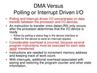
SPIM output • Similar to the input, SPIM has two memory locations for output • 0xffff0008: Transmitter control. • Bit 1: interrupt enable • Bit 0: ready • 0xffff000c: Transmitter data. • Bit 0-7: data byte
SPIM output • If you need to show something on the console, do the following: • Check if ready bit is 1. If yes, proceed. Otherwise, wait. • Write to the data. The ready bit will be reset to 0, and will be set to 1 after the byte is transmitted.
question • Is this the most efficient way to do it? • Remember that the processor usually has a lot of things to do simultaneously
Interrupt • The key problem is that the time when the input occurs cannot be predicted by your program • Wouldn’t it be nice if you could “focus on what you are doing” while be “interrupted” if some inputs come?
MIPS interrupt • For external interrupt, your code is executing, and if an event happens that must be processed, • The address of the instruction that is about to be executed is saved into a special register called EPC • PC is set to be 0x80000180, the starting address of the interrupt handler • Then, after processing this interrupt, call “eret” to set the value of the PC to the value stored in EPC
MIPS Interrupt • Is it okay to use $t0 in the interrupt? Note the difference between an interrupt and a function call. • For a function call, the caller is aware of the function call, so, it is not expecting the value of $t0 to be the same after the call. • For an interrupt, the user program is running and got interrupted. The user may not know about the interruption at all, so if you changed $t0 inside an interrupt, the user program may take the wrong value of $t0 and keep on calculating, which will result in errors. • Interrupt handlers should be short, because the processor often have multiple types of interrupts. It could happen that while you are processing interrupt A and interrupt B is triggered. Usually, in an interrupt handler, you disable other interrupts. To make sure that interrupt B can be processed in time, the handler for A should not take too long.
MIPS interrupt • Coprocessor 0 is a part of the CPU to handle interrupts. In SPIM, Coprocessor 0 contains the • BadVAddr (8), storing the memory address causing the exception • Count (9), increment by 1 every 10ms by default • Compare (11), if equals to Count, trigger an interrupt of level 5 • Status (12), • Bit 8-15: interrupt mask. A bit being ``1’’ means that this interrupt is enabled. • Bit 4: user mode. With SPIM, always 1. • Bit 1: exception level (EXL). Normally ``0,’’ set to ``1’’ if an exception occurred. When ``1,’’ no further interrupt is enabled and EPC is not updated. • Bit 0: interrupt enable. Enable (``1’’) or disable (``0’’) all interrupts. • Cause (13) • Bit 8-15: pending interrupts . A bit being ``1’’ means that this interrupt situation occurred, even if it is not enabled. • Bit 2-6: Exception code. ``0’’ is hardware interrupt. • EPC (14) • Config (16), config the machine • These registers can be read and modified using the instructions mfc0 (move from coprocessor 0) and mtc0 (move to coprocessor 0).
MIPS Interrupt • $k0 and $k1 are both used as temporary variables in interrupt servicing routines.
Code we used (Copy and paste it to an editor) .kdata # kernel data s1: .word 10 s2: .word 11 new_line: .asciiz "\n" .text .globl main main: mfc0 $a0, $12 # read from the status register ori $a0, 0xff11 # enable all interrupts mtc0 $a0, $12 # write back to the status register lui $t0, 0xFFFF # $t0 = 0xFFFF0000; ori $a0, $0, 2 # enable keyboard interrupt sw $a0, 0($t0) # write back to 0xFFFF0000; here: j here # stay here forever li $v0, 10 # exit,if it ever comes here syscall .ktext 0x80000180 # kernel code starts here .set noat # tell the assembler not to use $at, not needed here actually, just to illustrae the use of the .set noat move $k1, $at # save $at. User prorams are not supposed to touch $k0 and $k1 .set at # tell the assembler okay to use $at sw $v0, s1 # We need to use these registers sw $a0, s2 # not using the stack because the interrupt might be triggered by a memory reference # using a bad value of the stack pointer mfc0 $k0, $13 # Cause register srl $a0, $k0, 2 # Extract ExcCode Field andi $a0, $a0, 0x1f bne $a0, $zero, kdone # Exception Code 0 is I/O. Only processing I/O here lui $v0, 0xFFFF # $t0 = 0xFFFF0000; lw $a0, 4($v0) # get the input key li $v0,1 # print it here. # Note: interrupt routine should return very fast, so doing something like # print is NOT a good practice, actually! syscall li $v0,4 # print the new line la $a0, new_line syscall kdone: mtc0 $0, $13 # Clear Cause register mfc0 $k0, $12 # Set Status register andi $k0, 0xfffd # clear EXL bit ori $k0, 0x11 # Interrupts enabled mtc0 $k0, $12 # write back to status lw $v0, s1 # Restore other registers lw $a0, s2 .set noat # tell the assembler not to use $at move $at, $k1 # Restore $at .set at # tell the assembler okay to use $at eret # return to EPC