Download
1 / 22
230 likes | 505 Vues
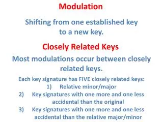
Modulation. Digital data can be transmitted via an analog carrier signal by modulating one or more of the carrier's three characteristics: amplitude frequency phase . Modulation.

E N D
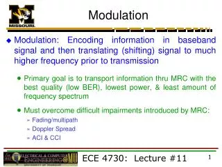
Modulation • Digital data can be transmitted via an analog carrier signal by modulating one or more of the carrier's three characteristics: • amplitude • frequency • phase
Modulation The carrier signal is usually just a simple, single-frequency sinusoid (varies in time like a sine wave). The basic sine wave :V(t) = Vo sin (2 p f t + f) V(t) ->the voltage of the signal as a function of time. Vo-> the amplitude of the signal (represents the maximum value achieved each cycle) f-> frequency of oscillation, the number of cycles per second F -> phase of the signal, representing the starting point of the cycle. To modulate the signal just means to systematically vary one of the three parameters of the signal: amplitude, frequency or phase.
Amplitude modulation Amplitude modulation is the simplest of the three to understand. The transmitter just uses the information signal, Vm(t) to vary the amplitude of the carrier, Vco to produce a modulated signal, VAM(t). Here are the three signals in mathematical form: Information: Vm(t) Carrier: Vc(t) = Vco sin (2 p fc t + f ) AM: VAM(t) = { Vco + Vm(t) }sin (2 p fc t + f) Here, we see that the amplitude term has been replaced by the combination of the original amplitude plus the information signal.
Amplitude Modulation The amount of modulation depends on the amplitude of the information signal. This is usually expressed as a ratio of the maximum information signal to the amplitude of the carrier. Modulation Index m = MAX(Vm(t) )/ Vco. If the information signal is also a simple sine wave, the modulation index will be m = Vmo/Vco. The interpretation of the modulation index, m, may be expressed as: The fraction (percentage if multiplied by 100) of the carrier amplitude that it varies by. If m =0.5, the carrier amplitude varies by 50 % above and below its original value. If m= 1.0 then it varies by 100%.
Modulation: Amplitude-Shift Keying (ASK) ASK encodes digital data by modulating the carrier's amplitude between two or more levels. Suppose a signal with amplitude 1 represents a binary 0 and a signal with amplitude 2 represents a binary 1. AM is more sensitive to noise than other modulation techniques => AM is not widely used in data transmission . A period is the amount of time before a wave repeats itself.
Modulation: Frequency-Shift Keying (FSK) Encodes digital data by modulating the carrier's frequency between two or more values. For example, a binary 0 would be one frequency (or group of frequencies) and a binary 1 would be some other frequency (or group of frequencies). FSK is less susceptible to corruption than ASK. Many modems use FSK to convert digital data to analogue signals.
Modulation: Phase-Shift Keying (PSK) Phase-shift keying encodes digital data by shifting the phase of the carrier. PSK-encoded data is highly resistant to corruption.
Demodulation Demodulation is the process of extracting the digital information from the carrier.
Multiplexing • Two type of multiplexing: • TDM - used in digital transmission • FDM - used in analogue transmission
Time-Division Multiplexing (TDM) In TDM system, the time of one channel is divided (usually evenly) among n users. Each user appears to have full channel for total time divided by n (time/n). Time division is the only multiplexing technique that can be used in a baseband line.
Frequency-Division Multiplexing (FDM) In frequency division multiplexing, the frequency of one channel is divided (usually evenly) among n users. It allows multiple, simultaneous transmissions. Bandwidth will be wasted if any user does not have any thing to send. Other users cannot take the advantage of additional available bandwidth.
Digital Signaling:Baseband & Broadband We can utilize potentially high bandwidth in one of the two ways: Baseband mode => all the available bandwidth is used to derive a single high bit rate (10 Mbps or higher) transmission path (channel). Broadband mode => the available bandwidth is divided to derive a number of lower bandwidth subchannels (and hence transmission paths) on one cable.
Baseband mode Baseband system uses direct digital signaling. The digital signal fully occupies the cable, which constitutes a single channel. On a typical baseband network, each device transmits bi-directionally. Baseband networks have a limited range, due to attenuation, and noise. Repeaters may be used to extend the length of a baseband system, and must use 50-ohm cable.
Broadband mode Broadband systems use analog signaling with the use of high frequency carrier, which is modulated with the digital signals, video and sound. The transmitting device uses different carrier frequency than the receiving device. The transmission is unidirectional with 75-ohm coaxial cable. Frequency-Division Multiplexing (FDM) is used in Broadband transmission. Each channel centers on a different carrier frequency. For example, on a Cable TV, with a bandwidth of 500 MHz can carry more than 80 television channels (of 6-MHz bandwidth each). Further multiplexed within each 6-MHz band are the channel's own audio subcarrier, video subcarrier and color subcarrier
Digitization Analogue voice transmission is limited to a maximum bandwidth of less than 4KHz. To convert such signals into digital form, their amplitude must be sampled at a minimum rate of twice the highest frequency component. Hence to convert a 4KHz voice signal into digital form, it must be sampled at 8000 times per second.
Digitization . The amplitude of each pulse being equal to the amplitude of the original analogue signal at the sampling instant. The resulting signal is thus known as a pulse amplitude modulated or PAM signal.
Digitization • The PAM signal is still analogue since its amplitude can vary over • the full amplitude range. • It is converted into an all-digital form by quantizing each pulse • into its equivalent binary form. • Eight binary digits (bits) are used to quantize each PAM signal • which include one bit to indicate the sign of the signal (positive • or negative). • This means 256 distinct levels are used. 00 -> FF = 256 distinct • levels. • The resulting digital signal has a bit rate of 64000 • = 8 * 8000 bits per second
Digital encoding Most LANS transmit digital data in digital signals. To do this, transmitter and receiver must accurately determine when each signal element occurs and what its value is. Clock must be used in which the sender and the receiver agree on. Lots of digital encoding technique exists, here are few of them: • UNIPOLAR: • Bits are transmitted as 힕 for binary 0 and 0V as binary 1. (old teletype machine)
Digital encoding • POLAR: • Same as RS-232-C standard.
Digital encoding • MANCHESTER Coding: • High-to-Low mid-bit transition for 0 input with the clock, and low-to-high mid-bit transition for 1 input with the clock.(input means the raw signal). Both transitions must be synchronized with the clock between the sender and the receiver • . Manchester Coding is used in Ethernet LANs
Digital encoding • Differential Manchester Coding: • Encoding is done by the presence of a transition for binary 0, and the lack (absence) of a transition as binary 1. Encoding starts at the beginning of the bit cell, if input is zero, it will be represented with a transition, and at mid-bit cell encoding follows the clock. If input signal starts with binary 1, then no transition is encoded, but it follows the clock at mid-bit cell • .