Download
1 / 18
180 likes | 184 Vues
This presentation discusses the latest advancements in research and development for the International Linear Collider (ILC) detector, including physics and machine studies, detector resolution standards, hardware proof-of-principle, and reconstruction capabilities.

E N D
SCIPP R&D on the International Linear Collider Detector DOE Site Visit June 28, 2005 Presenter: Bruce Schumm
Activity is increasing, with studies now on four fronts: • Physics and machine studies for e-e- running • Detector resolution standards from physics simulation • Hardware proof-of-principle of low-mass silicon tracking • Reconstruction capabilities of all-silicon tracking Current involvements (all very much part time) 3 senior physicists, 2 post-docs, 2 graduate students, 4 undergraduate thesis students, 1 Engineer, 1 technical staff, one bored housewife.
Detector Resolution Standards from Selectron Production Participants: Senior Physicist Bruce Schumm Undergraduate Thesis Students Troy Lau*, Joseph Rose, Matthew Vegas, Eric Wallace Community Member (on hold before Grad School) Ayelet Lorberbaum *Recipient of two Undergraduate Research Awards; grad school at U. Michigan this fall.
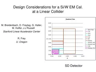
Original Motivation To explore the effects of limited detector resolution on our ability to measure SUSY parameters in the forward (|cos()| > .8) region. SiD Tracker
SPS 1 Spectroscopy: At Ecm = 1Tev, selectrons and neutralino are light. selectrons • Beam/Brehm: • √smin=1 • √smax=1000 • = .29 sz = .11 (mm) LSP
Selectrons vs. cos() SPS1A at 1 TeV Roughly ½ of statistics above |cos()| of 0.8, but… Electrons vs. cos()
Electron energy distribution with beam/bremm/ISR (.16%). No detector effects or beam energy spread. Upper Endpoint Lower Endpoint • sample electron energy distribution Mselectron = 143.112 (SPS1A)
The spectrum is weighted towards higher energy at high |cos()|, so there’s more information in the forward region than one might expect.
Determine the selectron mass accuracy in both the central (0 < |cos| < 1) and full (0 < |cos| < 1) region
Detailed Simulation of SiD Tracking System (and SiD variants) Participants: Senior Physicist Bruce Schumm Graduate Students Christian Flacco, Luke Winstrom, Michael Young* *Supported primarily through department (TA) funds; work deemed important enough that SLAC is paying for ½ of his support this summer.
Detailed Simulation of SiD Tracking System (and SiD variants), continued Two areas of work: Pulse Development Simulation Provides simulation of pulse development and amplification. Will soon be incorporated in international simulation framework (awaiting “hook” from Norman Graf at SLAC) SiD Tracking Capabilities Explore tracking performance of five-layer SiD tracker, as well as that of 8-layer variant
Pulse Development Simulation Long Shaping-Time Limit: strip sees signal if and only if hole is col- lected onto strip (no electrostatic coupling to neighboring strips) Charge Deposition:Landau distribution (SSSimSide; Gerry Lynch LBNL) in ~20 independent layers through thickness of device Geometry:Variable strip pitch, sensor thickness, orientation (2 dimen- sions) and track impact parameter Lorentz Angle:18 mrad per Tesla (holes), from measurements
Carrier Diffusion Hole diffusion distribution given by Offest t0 reflects instantaneous expansion of hole cloud due to space-charge repulsion. Diffusion constant given by mh = hole mobility Reference: E. Belau et al., NIM 214, p253 (1983)
Electronics Simulation Detector Noise: From SPICE simulation, normalized to bench tests with GLAST electronics Analog Measurement: Employs time-over-threshold with variable clock speed; lookup table provides conversions back into analog pulse height (as for actual data) RMS Gaussian Fit Detector Resolution (units of 10m)
Hardware Development of Long Shaping-Time strip Readout for the Linear Collider Detector Senior Physicists Alex Grillo, Bruce Schumm Post-Doctoral Fellows Jurgen Kroseberg, Gavin Nesom Technical Staff Ned Spencer*, Max Wilder * Lead Engineer
Li Hi Li+1 Hi+1 Li+2 Hi+2 Li+3 Hi+3 Li+4 Hi+4 Li+5 Hi+5 Li+6 Hi+6 Proposed LSTFE Back-End Architecture Low Comparator Leading-Edge-Enable Domain 8:1 Multi-plexing (clock = 50 ns) FIFO (Leading and trailing transitions) Event Time Clock Period = 400 nsec
FIFO FIFO FIFO Controller FIFO FIFO FIFO Proposed LSTFE Back-End Architecture (cont’d) Per 128 Channel Chip: 1 Master FIFO reads out 32 local FIFO’s Store in Master FIFO essentially complete by end of ~1ms beam spill Master FIFO