Download
1 / 41
410 likes | 419 Vues
The 80x86 Programming Model. The Flag Register. Z (zero): This flag is set to one if the result of the last arithmetic or logic instruction is zero.

E N D
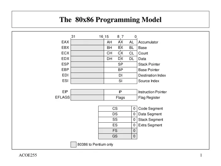
The Flag Register • Z (zero): This flag is set to one if the result of the last arithmetic or logic instruction is zero. • S (sign): This flag is set to one if the MSBit of the result of the last arithmetic or logic instruction is one, indicating a negative number . • C (carry): This flag is set to one if the last arithmetic instruction gave a carry out or a borrow in. • O (overflow): This flag is set to one if the result of the last arithmetic operation on signed numbers exceeded the capacity of the destination register.
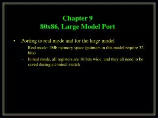
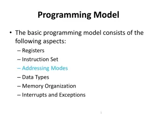
80x86 Modes of operation • Protected mode • Programs are given separate memory areas (segments) • Programs are not allowed to access memory outside of their segments • Real-address mode • Environment of 8086 processor • Direct access to system memory and hardware devices • The operating system could crash • System management mode • Provides an operating system for implementing power management and system security functions (computer manufacturers)
Assembler Directives • Directives are instructions given by the programmer to the assembler on how to assemble the program. • Directives are not part of the instruction set of the microprocessor. • The use of directives might vary from assembler to assembler. • Some of the MASM 6.12 assembler directives are: • ORG (Origin): Tells the assembler where to store the machine code of the next instruction. • EQU (Equate): Tells the assembler to assign a value to an identifier. • SEGMENT: Tells the assembler to begin a new segment. • ASSUME: Tell the assembler to associate a segment with a segment register. • PROC (Procedure): Tells the assembler to begin a new procedure. • MACRO: Assigns the sequence of instructions to an identifier. • END: Ends a program, segment (ENDS), a procedure (ENDP), or a macro (ENDM).
Data Definition Directives • Data Definition directives tell the assembler to store the specified data in the next memory locations. Data that occupies more than one location is stored with the LSByte in the lower address. • (DB) Define Byte (1 byte or 8 bits - Same as BYTE) • (DW) Define Word (2 bytes or 16 bits - Same as WORD) • (DD) Define Double Word (4 bytes or 32 bits - Same as DWORD) • (DQ) Define Quad Word (8 bytes or 64 bits - Same as QWORD) • (DT) Define Ten Bytes (10 bytes or 80 bits - Same as TBYTE) Examples: • ABC DB 26H ;ABC=26H • XYZ DB 35H,87H,0A4H ;XYZ= {35H,87H,A4H} • YOU DB ‘JOHN’ ;YOU = ‘JOHN’ • VAL DW 1254H ;VAL = 1254H • X1 DB ? ;X1 = UNSPECIFIED • X4 DB 3 DUP(20H) ;X4 = {20H,20H,20H} • N1 DB 123H ;INVALID
Data Definitions (Example) Show the content of the memory based on the following data definitions: ORG 100H VAL1 EQU 21H AB10 DB 37 NEW DB 23H,56H,’$’ LOT DW 1245H XY11 DB ‘NEXT’ A123 DD 123H B561 DB 4 DUP(40H) VAL2 DB VAL1
Format of DOS programs • All programs must have a code and a stack. • Code is the part of the program that contains the instructions of the program. • Stack is an area in the RAM used by the system to store return addresses, and by the programmer to store temporarily data. It is a Last In First Out (LIFO) buffer. • Programs can also have a data area, where all data (variables) is stored. • There are two basic types of programs: • Commands (.COM). The data and the stack of the program are part of the Code segment. The stack is always located at the end of the segment. The first 256 bytes of the segment are reserved. • Executable (.EXE). The code and stack and data of the program are located in different segments.
Format of the .COM programs CSEG SEGMENT PARA 'CODE’ ;Start a Code segment ASSUME CS:CSEG, DS:CSEG, SS:CSEG ORG 100H ;Reserve first 256 locations START: JMP MAIN ;Skip data area {Place the data of the program here} MAIN PROC NEAR ;Beginning of main procedure {Place the code of the program here} RET ;Get return DOS address MAIN ENDP ;End of main procedure CSEG ENDS ;End of the segment END START ;End of the program
Addressing Modes Addressing mode refers to the way the data needed by an instruction is specified.
Immediate Addressing Mode • The data needed is specified as a number in the machine code of a program. The data is specified by the programmer: • as a numeric operand in the instruction, e.g. MOV AL,87H ;AL 87H MOV CX,34A6H ;CX 34A6H MOV BL,8C2H ;Invalid (Data Mismatch) • or as a label. The actual value is determined by the assembler. e.g. MOV BX,OFFSET VAL3 ;BX Address of VAL3 MOV AH,CON1 ;AH CON1
Register Addressing Mode • Both of the operands are the contents of registers. e.g. MOV AL,BH ;AL BH MOV BX,CX ;BX CX MOV AX,DL ;Invalid (Data Mismatch) • Example:
Direct Addressing Mode • One of the operands is the contents of the memory location that is specified directly in the instruction. e.g. MOV AL,[1008H] ;AL [1008H] MOV BX,VALUE ;BX [VALUE]
Register Indirect Addressing Mode • One of the operands is the contents of the memory location that is specified by a register, or a combination of registers and an offset, in the instruction. • Index: Use of SI or DI to specify a memory location. e.g. MOV AL,[SI] ;AL [SI] • Base: Use of BX or BP to specify a memory location. e.g. MOV AH,[BP] ;AL [BP] • Base Relative: Use of BX or BP in combination with an offset to specify a memory location. e.g. MOV AL,[BX+ 2] ;AL [BX + 2] • Base Relative plus Index: Use of BX or BP in combination with an index register (SI or DI) and an offset to specify a memory location. e.g. MOV AL,[BX+SI+8] ;AL [BX+SI+8] MOV BX,ARR[BX+DI] ;BX ARR[BX+DI]
Examples • MOV ECX,6F23458H • MOV SI, -1 • MOV DS,1000H • MOV AL,100H • MOV 123,DH • MOV 0FABH,AX • MOV SI, CL • MOV EDX,ESI • MOV EDX,-2 Indicate whether or not each of the following MOV instructions is valid or invalid • MOV AX,BX • MOV DX,BL • MOV ECX,EDX • MOV SI,DI • MOV DS,AX • MOV AL,DH • MOV AX,DH • MOV IP,AX • MOV SI,CL • MOV EDX,AX • MOV AX,ES • MOV AX,16 • MOV DX,7F65H
Assembly Language Arithmetic and Logic Instructions
Arithmetic Instructions: (Addition) A. Addition: (Flags affected: A,C,O,P,S,Z) • ADD AL,BL ; AL AL + BL , BL unchanged • ADD CX,DI ; CX CX + DI , DI unchanged • ADD AH,45H ; AH AH + 45H • ADD [BX],AL ; [BX] [BX] + AL • ADD CX,[BX] ; CX CX + [BX] • ADD AL,CX ; INVALID B. Add with Carry: (Flags affected: A,C,O,P,S,Z) • ADC AH,BH ; AH AH + BH + Carry • ADC AX,CX ; AX AX + CX + Carry • ADC AL,[BX+SI] ; AL AL + [BX+SI] + Carry
Arithmetic Instructions: (Subtraction) C. Subtraction: (Flags affected: A,C,O,P,S,Z) • SUB AL,BL ; AL AL - BL ;BL unchanged • SUB CX,DI ; CX CX - DI ;DI unchanged • SUB AH,45H ; AH AH - 45H • SUB BL,ARRAY ; BL BL - [ARRAY] • SUB [BX],AL ; [BX] [BX] - AL • SUB AL,CX ; INVALID D. Subtract with Borrow: (Flags affected: A,C,O,P,S,Z) • SBB AH,BH ; AH AH - BH - Carry • SBB AX,CX ; AX AX - CX - Carry • SBB AL,[BX+SI] ; AL AL - [BX+SI] - Carry
Arithmetic Instructions: (Increment, Decrement) E. Increment: (Flags affected: A,O,P,S,Z) • INC AL ; AL AL + 1 • INC SP ; SP SP + 1 • INC COUNT1 ; [COUNT1] [COUNT1] + 1 • INC BYTE PTR[BX] ; [BX] [BX] + 1 • INC WORD PTR[BX] ; [BX] [BX] + 1 F. Decrement: (Flags affected: A,O,P,S,Z) • DEC AL ; AL AL - 1 • DEC SP ; SP SP - 1 • DEC COUNT1 ; [COUNT1] [COUNT1] - 1 • DEC BYTE PTR[BX] ; [BX] [BX] - 1 • DEC WORD PTR[BX] ; [BX] [BX] - 1
Examples • What will be the values of the carry, overflow, sign and zero flags after the execution of each of the following instructions: • MOV DX,0 • DEC DX • MOV AX,720H • SUB AX, 0E6H • MOV DX,0 • DEC DX
Arithmetic Instructions: (Multiplication) G. Multiplication: (Flags affected: C,O, (A,P,S,Z are undefined)) Unsigned multiplication: • MUL CL ; AX AL * CL • MUL CX ; DX,AX AX * CX • MUL BYTE PTR [BX] ; AX AL * [BX] • MUL WORD PTR [SI] ; DX,AX AX * [SI] Signed multiplication (2's complement): • IMUL BL ; AX AL * BL • IMUL BX ; DX,AX AX * BX • IMUL BYTE PTR [BX] ; AX AL * [BX] • IMUL WORD PTR [SI] ; DX,AX AX * [SI]
Arithmetic Instructions: (Division) H. Division: (Flags affected: A,C,O,P,S,Z (all undefined)) Unsigned Division: • DIV CL ; AL Quotient of AX/CL ; AH Remainder of AX/CL • DIV CX ; AX Quotient of DX,AX/CX ; DX Remainder of DX,AX/CX Signed Division: • IDIV CL ; AL Quotient of AX/CL ; AH Remainder of AX/CL • IDIV CX ; AX Quotient of DX,AX/CX ; DX Remainder of DX,AX/CX
Arithmetic Instructions: (BCD and ASCII Operations) I. BCD and ASCII Arithmetic: • DAA ; Decimal Adjust for Addition • DAS ; Decimal Adjust for Subtraction • AAA ; ASCII Adjust for Addition • AAS ; ASCII Adjust for Subtraction • AAM ; ASCII Adjust for Multiplication • AAD ; ASCII Adjust for Division
Logic Instructions:(AND, OR, XOR, NOT, NEG and TEST) Logic Instructions: • AND AL,BL ; AL AL AND BL (Always clears C and O flags) • AND CL,33H ; CL CL AND 33H • AND AX,[DI] ; AX AX AND [DI] • OR AL,BL ; AL AL OR BL • OR AX,1234H ; AX AX OR 1234H • XOR AL,CL ; AL AL EX-OR CL • XOR BH,0FH ; BH BH EX-OR 0FH • NOT CH ; CH 1's complement of CH (No flags affected) • NOT AX ; AX 1's complement of AX • NEG CH ; CH 2's complement of CH (ALWAYS SETS CF) • NEG BX ; BX 2's complement of BX • TEST AL,30H ;Perform AL AND30H and set the flags. AL is unchanged.
Program Control Instructions :(Jump and Call) Unconditional jump (JMP): • The JMP instruction specifies the address of the next instruction to be executed. There are three types of unconditional jump instructions: the SHORT, the NEAR, and the FAR. A SHORT jump is specified with only one byte which represents the displacement between the current instruction to the next instruction. The next instruction can be located at a distance from +127 to -128 memory locations away from the current instruction. A NEAR jump specifies the address of the next instruction within the current Code Segment. A FAR jump specifies the exact address of the next instruction by specifying the values of the CS and IP registers. • Examples: • JMP NEXT • JMP SHORT AGAIN • JMP NEAR AGAIN • JMP FAR AGAIN
Program Control Instructions :(Jump and Call) Conditional jump: • Conditional jumps are executed only if the specified conditions are true. Usually the condition specified by a conditional jump instruction is the state of a flag. A list of the conditional jump instructions that check the state of flags is given below: InstructionFlags testedAction JC C = 1 Jump if carry set JZ Z = 1 Jump if equal or zero JS S = 1 Jump on sign (Negative) JO O = 1 Jump on overflow JNC C = 0 Jump if not carry JNZ Z = 0 Jump if not equal or 0 JNS S = 0 Jump if not sign (Positive) JNO O = 0 Jump if not overflow
Program Control Instructions :(Jump and Call) Conditional jump using the Compare instruction: • Conditional jump instruction can be used after the compare ( CMP ) instruction. • Comparison of unsigned numbers is done using the Above or Below conditions. For example 81H is Above 7EH since 129>128. • Comparison of unsigned numbers is done using the Greater or Less conditions. For example 81H is Less than 7EH since -127<128. • The programmer can choose between the Above/Below or Greater/Less according to the application. If the values used in a program are always positive then these values are treated as unsigned numbers, and the Above /Below conditions are used, otherwise signed numbers are used and the Greater/Less conditions are used..
Program Control Instructions :(Jump and Call) A list of the conditional jump instructions used with the Compare instruction is given below: InstructionFlags testedAction JA C = 0 & Z = 0 Jump if above JAE C = 0 Jump if above or equal JB C = 1 Jump if below JBE C = 1 or Z = 1 Jump if below or equal JE or JZ Z = 1 Jump if equal or zero JG O = Z AND S Jump if greater JGE S = O Jump if greater or equal JL S = O Jump if less JLE Z = 1 or S = O Jump if less or equal JNE or JNZ Z = 0 Jump if not equal or 0
Program Control Instructions :(Jump and Call) Loops: • The LOOP instruction is a combination of the conditional jump and the decrement CX instructions. It will decrement the contents of CX and, if CX is not zero, jump to the label associated with the LOOP. If CX becomes zero, then the next sequential instruction is executed. • The LOOP instruction can also have conditional forms LOOPE (LOOPZ), and LOOPNE (LOOPNZ). • The conditional jump instruction JCXZ (Jump if CX = 0) can also be used. Procedures: • Procedures are implemented by using the PROC directive. The last instruction in a procedure must be the RET instruction. A procedure can be called by using the CALL instruction.
Shift instructions • SHL AL, BL ;Shifts the contents of AL to the left as many times as the value of BL, filling the lowest bit with zero and moving the highest to the carry flag • SHR AL, BL ; The same principle, but now a right shift
Arithmetic shifts • SAL AL, BL ;Identical to SHL • SAR AL, BL ;Shift right, but the most significant bit fills the leftmost position again
Rotate instructions • ROL • ROR
Rotate with carry instructions • RCL • RCR