Download
1 / 18
180 likes | 351 Vues
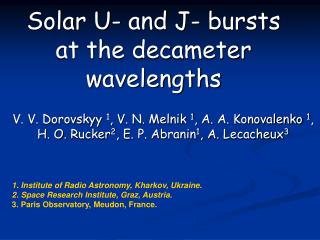
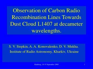
S olar corona observations at decameter wavelengths. Artem Koval koval2211@rambler.ru Institute of Radio Astronomy Kharkov, Ukraine. 2. Introducton. Solar radio emission consists of two components: thermal (continuum “background” radiation)

E N D
Solar corona observations at decameter wavelengths Artem Koval koval2211@rambler.ru Institute of Radio Astronomy Kharkov, Ukraine
2 Introducton • Solar radio emission consists of two components: • thermal (continuum “background” radiation) • non-thermal (bursts, noise storms, flares and other disturbing features) • The observations of the quiet Sun at decameter wavelengths are imposed restriction by the fact that the radiation is much weaker in comparison with the burst activity. • Thus, the principal requests for radio astronomical instrument are very large dynamic range and high sensitivity as well as carrying-out observations during periods of reduced activity (sunspot minimum). • UTR-2 radio telescope is an appropriate instrument satisfying basic demands
3 Quiet-Sun Radio Emission: Overview of Observations Frequency Radio astronomical (MHz) Reference instrument _ 80.0 Sheridan (1970) Culgoora Radio Heliograph 60.0 Aubier et al. (1971) Arecibo Radio Telescope 36.9 Aubier et al. (1971) – 29.3 Aubier et al. (1971) – 25.0 Abranin et al. (1976) UTR-2 Radio Telescope 73.8 Kundu et al. (1977) Clark Lake Radio Telescope 26.3 Kundu et al. (1977) – 73.8 Erickson et al. (1977) – 57.7 Erickson et al. (1977) – 38.1 Erickson et al. (1977)– 25.8 Erickson et al. (1977) – 19.0 Erickson et al. (1977) – 73.8 Thejappa & Kundu (1992) Clark Lake Radio Heliograph 50.0 Thejappa & Kundu (1992) – 38.5 Thejappa & Kundu (1992) – 75.0 Ramesh et al. (2000) Gauribidanur Radio Telescope 34.5 Subramanian (2004) – 77.0 Ramesh et al. (2006) – 51.0 Ramesh et al. (2006) –
4 UTR-2 Radio Telescope, Ukraine Effective area 150000 m2 N-S and E-W arms 12 sections Frequency band 8-33 MHz The beam sizes ~25´× 25´
5 Experimental equipment 1 N 2 Digital Signal Processor 3 DSP W 4 12 9 10 11 5 6 7 S 8 - declination - hour angle UTR-2 antenna array • latitude of UTR-2
6 DSP block scheme Visual data presentation Hard disk + GPS receiver Channel1 ADCblock FPGA matrix SOFTWARE Channel 2
7 DSP characteristics ADC sampling frequency 66 MHz Operating bandwidth 8-33 MHz Max. number of output frequency channels 8192 Frequency resolution 4 kHz Time resolution from 0.2 msec up to 1 sec Dynamic range 90 dB
8 Multi-beam scanning Pencil-shaped beams Date Number of scans September, 2010 per day North 25´ V 4 10 5 9 IV 6 7 III Total number: 26 The scanning was realized using these beams II I 25´ South
9 One-dimensional scans of the quiet Sun Example of time-frequency profiles from scans along solar equator on September 6, 2010. Time zero corresponds to 08:59:15 UT
10 Solar spectrum of quiet Sun (corona) at decameter wavelengths The equation of the line:
11 Nancy RH, NDA LOFAR RATAN-600 RH, SSRT Chiniese RH OVRO Clark Lake Nobeyama RH Ukraine RH Gauribidanur RH Culgoora RH
13 Principle of heliogram construction N Multi-beam UTR-2 regime: Ω(θ, φ) ≈ 25´× 25´ at 25 MHz V IV III Extra phase shift module – fast change of antenna pattern position alongU. II I S I II III IV V VI VII VIII W E
14 Heliograph field of view Separating markers Time of cadre composition 0.24 sec, 2 min 4 min Number of image elements 58 The field sizes ~ 2.5 3.3
15 Examples of heliographic observations 3C123 (Freq. 21 MHz; September 3, 2010) 3C348 (Freq. 21 MHz; August 29, 2010)
16 Examples of heliographic observations Solar corona (Freq. 21 MHz; August 29, 2010; 07:20 UT)
17 Conclusion • The two-dimensional heliograph of decameter wavelengths represents unique radio astronomical tool (the most low-frequency and multichannel) . • The radio heliograph is capable to produce the images of the “quiet” Sun as well as to track for displacement of radiation sources in the solar corona. • The preliminary results of heliographic observations of point sources (3C123, 3C348) as well as solar corona are presented. • The new working mode of the UTR-2 radio telescope – one dimensional heliograph – has been introduced as a supplementary, multitasking tool for radio astronomical measurements, in particular to investigate a radio emission from the “quiet” Sun. • The values of integrated flux density were obtained and extended to long- wavelength region of “quiet” Sun radiation spectrum indicating good agreement with results in others (meter and so on) wavelengths.