Download
1 / 4
40 likes | 167 Vues
Mechanical design for the PBPM. 4 electrodes only, for simplicity. SMC connectors. Ceramic vacuum chamber with resistive coating Bellow allowing 0.3 or 1 mm misalignment (depending on length). Helicoflex vacuum seals. Titanium coating. Φ 6 mm. Resolution: 100 nm. Aperture: 4-6 mm.

E N D
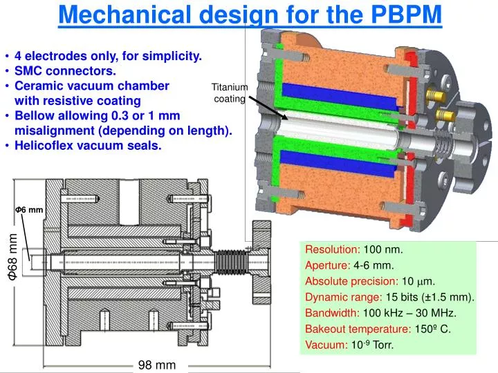
Mechanical design for the PBPM • 4 electrodes only, for simplicity. • SMC connectors. • Ceramic vacuum chamberwith resistive coating • Bellow allowing 0.3 or 1 mm misalignment (depending on length). • Helicoflex vacuum seals. Titanium coating Φ6 mm Resolution: 100 nm. Aperture: 4-6 mm. Absolute precision: 10 mm. Dynamic range: 15 bits (±1.5 mm). Bandwidth: 100 kHz – 30 MHz. Bakeout temperature: 150º C. Vacuum: 10-9 Torr. Φ68 mm 98 mm
The response of the PBPM Simulation of beam horizontal movement using wire method in HSSS S21 • Simulations show: • Expected non-linearity of D- signal. • Unexpected non-linearity of the S-signal. • Good linearity of D/S. • More simulations will follow to better understanding and optimization. S11
Longitudinal impedance and thin film coating High frequency simulations with PSPICE1) • Thin film diameter: 6 mm. • Outer ceramics diameter: 10 mm. • Electrodes inner diam.: 13 mm. • Length: 50 mm. • The high frequency longitudinal impedance is determined by the titanium coating, and is at present 11 ohms. • There appear some bumps in the region around 1 GHz unlike the existing CTF3 version. • Simulations show they can be damped reducing the ratio between the diameters (smaller coaxial impedances). • The cut-off frequency is always higher than the specifications. Electrodes current Impedance Titanium current fcutoff Rcoating= 11.2 Ω fcutoff = 226.8 MHz 1) Using the model described in M. Gasior, CERN-AB-2004-092; CLIC-Note-611
Outlook • Optimize and set all the geometrical parameters. • Optimize and set the value of the thin film. • Optimize the linearity (in relation with the geometrical parameters). • Simulation of the wakefields or calculation from the longitudinal impedance in PSPICE. • Optimize the design of the alignment support. • Launch the mechanical fabrication of one prototypes. Critical components designed. Feedback and offers from companies obtained. • Construct the test bench. • Follow-up of the electronics design of the signal treatment. The goal is to achieve more than 90 dB CMRR at 30 MHz. • Publish report by end of May 2006.