Download
1 / 36
370 likes | 637 Vues
Distributed Routing Algorithms for Underwater Acoustic Sensor Networks. Dario Pompili , Tommaso Melodia and Ian F. Akyildiz. What is an Acoustic Sensor Network?. Acoustic (definition) - Relating to sound or the sense of hearing .

E N D
Distributed Routing Algorithms for Underwater Acoustic Sensor Networks Dario Pompili, TommasoMelodia and Ian F. Akyildiz
What is an Acoustic Sensor Network? • Acoustic (definition) - Relating to sound or the sense of hearing. • Acoustic Sensor Networks (ASN) are networks where the communication between sensor nodes is done using sound waves instead of radio or optical waves. • ASN are specially useful for setting up underwater sensor networks (UW-ASN).
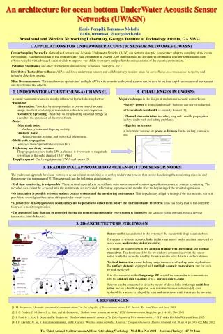
Why Underwater Acoustic Sensor Networks (UW-ASN)? • High attenuation (weakening) of radio waves underwater (when distance > 100 m). • High scattering of optical waves underwater (when distance > 100 m). • Sound waves can travel more efficiently underwater without suffering from high attenuation and scattering (compared to radio and optical waves).
Applications of UW-ASNs • Oceanographic data collection • Ocean sampling • Pollution and environmental monitoring • Offshore exploration • Disaster prevention • Assisted navigation • Distributed tactical surveillance • Mine reconnaissance
Why new protocol for UW-ASNs? • Many protocols for terrestrial WSNs (usually radio based). • Unique characteristics of underwater acoustic channel: • Limited bandwidth capacity • High propagation delays
Design challenges of UW-ASNs • Propagation delay is five orders of magnitude higher than in radio frequency (RF) terrestrial channels, which is due to the low speed of sound (1500 m/s underwater). • The underwater acoustic channel is severely impaired, especially due to multipath and fading problems. • Available bandwidth is distance dependent and in general is limited to few tens of kHz due to high environmental noise at low frequencies (lower than 1 kHz) and high transmission loss at high frequencies (greater than 50 kHz).
Design challenges of UW-ASNs • High bit error rates and temporary losses of connectivity can lead to the formation of ‘shadow zones’*. • Underwater sensors are prone to failures because of fouling and corrosion. • Batteries are energy constrained and cannot be recharged (solar energy cannot be exploited underwater). *Shadow zones – underwater regions where the signal reception is impaired due to deep signal dips and fading caused by multipath.
Proposed solution • Two bandwidth and energy efficient distributed geographical routing algorithms, designed to meet the application requirements of: • Delay-insensitive static underwater sensor networks. • Delay-sensitive static underwater sensor networks.
Proposed solution • Routing solutions are tailored for the characteristics of the 3D underwater environment. • They take into account: • Very high propagation delay, which may vary in horizontal and vertical links. • Different components of the transmission loss. • Impairment of the physical channel. • Limited bandwidth. • High bit error rate. • If protocols are not specifically designed, it may lead to very low utilization of underwater acoustic channel.
Primary objectives • Increasing the efficiency of the acoustic channel – requires longer packets. • Limiting the packet error rate on each link – requires smaller packets. • These conflicting requirements are solved by making the sender send a train of short packets back-to-back without releasing the channel.
Routing algorithm overview • For every packet sent, each node jointly selects its: • Best next hop. • Optimal transmit power. • Forward error correction (FEC) rate. • The objective of above selections is to minimize the energy consumption, while taking the condition of the underwater channel and the application requirements into account. • Proposed solutions are tailored for static networks and do not account for mobility issues. However their distributed nature helps in case of mobility.
Routing algorithm overview • The optimal packet size is set off-line (for system simplicity and ease of sensor buffer management). • On-line adjustment of the strength of the FEC technique when channel coding is performed by tuning the amount of FEC redundancy according to the dynamic channel conditions. • When the amount of FEC redundancy increases, the packet payload used for data decreases (as packet size is set off-line).
Communication architecture & Network models • Three-dimensional underwater sensor networks. • Sensor nodes float at different depths to observe a given phenomenon that cannot be adequately observed by means of ocean bottom sensor nodes. • Represented as a directional graph 𝒢(𝒱, ℰ) • 𝒱 = {𝑣1, .., 𝑣𝑁} is a set of nodes, with 𝑁 = ∣𝒱∣. • ℰ is the set of directional links among nodes. • 𝑒𝑖𝑗∈ ℰ equals 1 if node 𝑣𝑗 is in the neighborhood of node 𝑣𝑖. • 𝑒𝑖𝑗and 𝑒𝑗𝑖 may not have the same value as underwater links may be asymmetric. • Node 𝑣𝑁 represents the sink, i.e., the surface station.
Communication architecture & Network models • Each link 𝑒𝑖𝑗 is associated with its: • Distance 𝑑𝑖𝑗 in meters. • Expected propagation delay in seconds (i.e. ratio of distance and acoustic propagation speed of link (𝑖, 𝑗)). • Transmission loss – the acoustic intensity decreases as an acoustic pressure wave propagates outwards from a sound source. • Geometric spreading. • Medium absorption. • Transmission anomaly.
Channel Efficiency & Packet Train • Acoustic channel utilization efficiency – the net bit rate achievable on a link when considering packet retransmissions due to channel impairments. • Increase in efficiency of the acoustic channel by transmitting a train of short packets back-to-back. • Limiting the packet error rate by keeping the length of the transmitted packets short.
Why packet train? • Analysis of the performance of the single-packet transmission scheme in underwater channels reveal the following problems: • The channel utilization efficiency is very low. • Underwater communications greatly benefit from the use of forward error correction (FEC) and hybrid automatic request (ARQ) mechanisms. It considerably decreases the average number of transmissions. • The channel efficiency depends on the packet size and drops with increasing distance. • Therefore packet train.
Benefits of packet train • Allows increasing the efficiency of the acoustic channel by increasing the length of the transmitted train without compromising on the packet error rate, i.e., keeping the transmitted packets short. • Decouple the effect of the packet size from the choice of the length of the train.
Delay-insensitive routing algorithm • Distributed geographical routing solution for delay-insensitive underwater applications. • Geographical routing protocols assume that nodes can either work in greedy mode or in recovery mode. • Recovery mechanisms are out of scope. The protocol assumes that no void regions exist.
Delay-insensitive routing algorithm • In a distributed manner and only exploiting a local view of the network, it allows each node to jointly select its best next hop, the transmitted power, and the FEC code rate for each packet. • The objective is efficient channel utilization and minimizing the energy consumption. • It tries to exploit those links that guarantee a low packet error rate in order to maximize the probability that the packet is correctly decoded at the receiver. • Energy efficiency of the link is weighted by the number of retransmissions required to achieve link reliability, with the objective of saving energy.
Delay-insensitive routing algorithm distance independent energy to transit one bit fixed header size of a packet maximum transmitted power fixed optimal packet size bit rate expected noise at node 𝑗 positive advance set, composed of nodes closer to sink 𝑁 than node 𝑖 neighbor set of node 𝑖 transmitted power Best next hop. Selected based on minimum energy required to successfully transmit a payload bit from node 𝑖 to the sink. minimum energy required to successfully transmit a payload bit from node 𝑖 to j energy to transmit one bit from 𝑖 to 𝑗 variable FEC redundancy that is included in each packet transmitted from node 𝑖 to node 𝑗 average number of transmissions of a packet sent by node 𝑖 such that the packet is correctly decoded at receiver 𝑗 estimated number of hops from node 𝑖 to the surface station (sink) 𝑁 when 𝑗 is selected as next hop variable FEC redundancy that is included in each packet transmitted from node 𝑖 to node 𝑗 bit error rate on link (𝑖, 𝑗) packet error rate on link (𝑖, 𝑗)
Summary – Delay-insensitive routing algorithm • Allows a node 𝑖 to select a node j* (among its neighbors) as next hop that satisfies the following two requirements: • It is closer to the surface station than 𝑖. • It minimizes the link metric i.e. minimum energy required to successfully transmit a payload bit from node 𝑖 to the sink, taking the condition of the underwater channel into account, when 𝑖 selects 𝑗 as next hop. • While this heuristic approach does not guarantee global optimality as a sender does not have a global view of the network, it achieves the ‘best’ possible performance given the limited information at the sender.
Delay-sensitive routing algorithm • Similar to the delay-insensitive routing algorithm except that it includes two new constraints to statistically meet the delay-sensitive application requirements: • The end-to-end packet error rate should be lower than an application-dependent threshold . • The probability that the end-to-end packet delay be over a delay bound 𝐵𝑚𝑎𝑥, should be lower than an application-dependent parameter 𝛾. • Does not retransmit lost or corrupted packets at the link layer.
Delay-sensitive routing algorithm • Time-stamps packets when they are generated by a source so that they can be discarded when they expire. • To save energy, while statistically limiting the end-to-end packet delay, it relies on an earliest deadline first scheduling, which dynamically assigns higher priority to packets closer to their deadline.
Delay-sensitive routing algorithm fixed number of packets transmitted in a train on each link network queuing delay estimated by node 𝑖 when 𝑗 is selected as next hop time-to-live of packet 𝑚 arriving at node 𝑖
Delay-sensitive routing algorithm Statistical Link Delay Model Constraint that each link needs to meet in order to statistically bound the end-to-end packet delay. Forces the packet error rate 𝑃𝐸𝑅𝑖𝑗 that will be experienced by packet 𝑚 on link (𝑖, 𝑗) to respect the application end-to-end packet error rate requirement. estimated number of hops to reach the sink if 𝑗 is selected as next hop
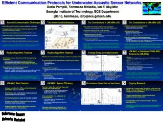
Performance Evaluation • Extended the wireless package of the J-Sim simulator, which implements the whole protocol stack of a sensor node, to simulate the characteristics of the 3D underwater environment. • Modeled the underwater transmission loss, the transmission and propagation delays of vertical and horizontal links, and the physical layer characteristics of underwater receivers. • Performed three sets of experiments to analyze the performance of the proposed routing solutions.
Performance Evaluation • Scenario 1: Delay-insensitive Background Traffic • Simulate a low-intensity delay-insensitive background monitoring traffic from a small 3D volume (100x100x100 m^3). • Scenarios 2 and 3: Comparison Between Delay-insensitive and Delay-sensitive Event-driven Traffic • Only some sensors inside an event area of spherical radius 100 m (centered inside the 3D monitoring volume) are sources of data packets of size equal to 500 and 100 Bytes for delay-insensitive and delay-sensitive applications, respectively.
Performance Evaluation • Full Metric– minimize transmission energy. • No Channel Estimation – does not consider the channel condition. • Minimum Hops – minimizes the number of hops to reach the surface station. Scenario 1: Delay-insensitive routing. Average node residual energy vs. time, for different link metrics.
Performance Evaluation Scenario 1: Delay-insensitive routing. Average packet delay vs. time, for different link metrics.
Performance Evaluation Scenario 2: Delay-insensitive routing. Packet delay and average delay vs. time for three source rates. (a): Source rate equal to 150 bps; (b): Source rate equal to 300 bps; (c): Source rate equal to 600 bps.
Performance Evaluation Scenario 3: Delay-sensitive routing. Packet delay and average delay vs. time for three source rates. (a): Source rate equal to 150 bps; (b): Source rate equal to 300 bps; (c): Source rate equal to 600 bps.
Limitations • The protocols are designed for networks with static nodes (mobility not specifically considered). • If the acoustic channel has high error rate, the network goodput would decrease because the FEC rate will increase and the amount of data in each packet will decrease (as the packet size is fixed offline). • The protocol assumes that there are no voids in the network i.e. greedy routing is always possible (though recovery techniques can be used, they are out of scope).
Conclusion • The problem of data gathering in a 3D underwater acoustic sensor network was investigated. • Two distributed geographical routing algorithms for delay-insensitive and delay-sensitive applications were introduced and evaluated through simulations. • Objective is to minimize the energy consumption while taking the varying condition of the underwater acoustic channel and the different application requirements into account.