Download
1 / 15
150 likes | 349 Vues
Creating a transmission line model of the QuattroTank. By A. Arnold with thanks t o O. Berrig. What is the QuattroTank ?. The QuattroTank (QT) is an SPS component that is used as a testbed for crystal collimation. 142mm.

E N D
Creating a transmission line model of the QuattroTank By A. Arnold with thanks to O. Berrig
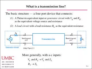
What is the QuattroTank? The QuattroTank (QT) is an SPS component that is used as a testbed for crystal collimation. 142mm • The QT has a relatively simple internal structure, and is more or less only constructed out of a single material. When taking wire measurements of the QT, most of the structure takes the form of a coaxial cable • For these reasons, it is an ideal test structure for developing a model for wire measurements
How was the QuattroTank modelled? • Transmission line theory was used as a basis for the models • Included in the models are the effects of SUCOBoxes (pictured) and matching resistors, which are used in wire measurements. In total, three different models were made, capturing different effects • We try to understand the following features of wire measurements of the QT: • The distortions introduced by the SUCOBoxes • Imperfections in the resistor setup • The main resonant peaks
Why use transmission line theory? • With a wire stretched longitudinally in a piece of equipment, we essentially have a two-conductor transmission line. If our equipment is a cylindrical pipe, we now have a coaxial transmission line. • If our equipment consists only of segments with constant cross section, with only discontinuous changes in cross-section, then standard transmission line theory can be applied. That is, we can calculate a characteristic impedance for each of these sectionsand simply join the sections together in our model • For sections with continuously changing cross-section, we would need to apply some other method to discover the behaviour
First Model of the QuattroTank First, a model was constructed that did not take into account resonant peaks: The SUCOBoxes are modelled as lumped components; they contribute some series inductance and some capacitance to ground. The matching resistors are modelled as having a parasitic parallel capacitance. All other sections of the QT are modelled as simple transmission lines Although relatively complicated, all the lumped elements are to account for the effect of the SUCOBoxes and resistors. The values of the lumped elements were fitted to the data. Notice that a SUCOBox is only on port 1. The transmission line sections can simply be determined by the geometry.
Results of the first model As can be seen, the oscillations are modelled very well. The resonant peaks are not present in this model, so it seems the peaks are not a transmission line phenomenom. We also see that reflection on port 1 is significantly distorted compared to port 2. The resonant peaks take on a different character in S11. Notice that low-frequency phenomena are emulated well. If more time is spent tweaking the values of the lumped elements, a better match with the data could be possible Blue is the model and orange is the data. Note that the SUCOBox is on port 1.
Second Model of the QuattroTank Next, resonances were modelled with lumped RLC circuits in series: The values of the components in the RLC circuits were determined by fitting the height of the peak (to find R) and by the width of the peak (to find L/C). The resonant frequencies were taken to be 1.015 GHz and 1.4 GHz respectively.
Results of the second model In transmission, the resonant peaks seem to be modelled well. However, in reflection there is something strange – the direction of the second resonant peak is incorrect It is still unclear exactly why this is, but it is suspected that it is because the two peaks are different in nature. Blue is the model and orange is the data. Note that the SUCOBox is on port 1.
Fields of the resonant peaks in simulation Two CST simulations were made to try to identify the differences between the resonances; one is a wakefield simulation with no wire, and another is frequency domain with a wire. Clearly, the nature of these resonances differs. 1.32 GHz Wakefield 0.903 GHz Frequency Domain 1.40 GHz 1.018 GHz The shift in frequency between the wakefield and f-domain is expected to be caused by the wire. The longitudinal line in the wakefield pictures is the axis of the beam
Fields of the resonant peaks in simulation A few attempts were made to try to model the second resonant peak in a different way to the first, but all were unsuccessful. Perhaps because the resonance is more distributed across the structure, it cannot be modelled by a lumped circuit that sits within the structure.
Third Model of the QuattroTank A model was made for the QuattroTank with no matching resistors and no resonant circuits: This model treats the SUCOBoxes as transmission lines in of themselves
Results of the third model Now, without the complication of the matching resistors, we have even better agreement at low frequencies. An important point is that in this model, there is no guesswork as to the value of any parameters – we do not have to fit values of capacitance and inductance until our model matches. Blue is the model and orange is the data. Note that there are SUCOBoxes on both ports.
Conclusions • It is possible to model many of the phenomena seen in wire measurements using nothing more than transmission lines and lumped elements – more specifically we can model • The effect of SUCOBoxes, using parasitic capacitance and inductance • Some resonant peaks, with a lumped resonant circuit • General low-frequency oscillations due to the setup • In principle, because of the symmetric layout of the QuattroTank, S11 and S22 should be identical.The measurements show that S11 and S22 are not identical, which must be due to the SUCOBoxes. This is a problem because if we want to use Vaccaro’s correction formula, we actually require that they are identical. Also, we do not know how much S21 is distorted; this is also a problem because that is the signal we usually care about with wire measurements. Because of this, we should develop a way to install the wire and resistors without the use of SUCOBoxes. • There are two resonances in the QuattroTank, both are modelled well in transmission (S21, S12) with a lumped parallel RLC circuit, but for S11 and S22, only one of these peaks is modelled well by this.