Download
1 / 47
500 likes | 962 Vues
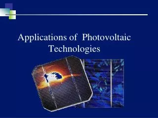
Applications of Photovoltaic Technologies. Losses. Electrical. Optical. Recombination. Ohmic. Reflection Shadowing Non-absorbed radiation. SC material Base Emitter Contact Material Metal Junction. Emitter region material, surface Base region material, surface

E N D
Losses Electrical Optical Recombination Ohmic Reflection Shadowing Non-absorbed radiation • SC material Base Emitter • Contact Material Metal Junction • Emitter region material, surface • Base region material, surface • Space charge region Summery of losses in Solar cell
Loss Electrical Optical Recombination Ohmic Reflection Shadowing Not-absorbed radiation • SC material Base Emitter • Contact Material Metal Junction • Emitter region material, surface • Base region material, surface • Space charge region Summery of losses in Solar cell
Substrate Typically Si, it can be different forms of Si, GaAs, CdTe, • Si is abundance in nature, non-toxic, dominate the micro-electronics industry but have low absorption coefficient Cell thickness Typically 200 to 500 m • Thinner cell are useful but difficult to handle, surface passivation becomes important Doping of base Typically 1 Ω-cm, P-type • Higher doping reduces resistive losses but carrier lifetime also decrease, reducing Voc Typical cell parameters
Emitter N-type, thickness < 1 m, doping 1019 #/cm3, 50-100 Ω/ □ • N-type material have better surface quality, high doping to reduce the emitter resistance, junction should be close to the surface Optical losses Typically ARC coating & surface texturing • about 80nm thick Si3N4 layer, Pyramid of about 4 to 5 m height Grid pattern 20 to 200 m wide fingers, 2 to 5 mm apart • Resistivity of Si is high, metal contact at the front and rear side is required to collect the current Typical cell parameters
Design tradeoffs: Efficiency Vs cost 15% 20% 25% High cell efficiencies are obtained in the laboratory using State-of-the-art technology in the lab produces 10% Module cost (Rs / W) But commercially mass produced cell efficiency lies between 13 – 16% research techniques used in the laboratory are not suitable for commercial production Cost of electricity (Rs / kWh) With higher efficiency modules, the cost per unit area can be much higher for a given cost target of electricity in kWh. (With high efficiency module additional costs, land, material are less.)
Solar PV Technologies Semiconductor Fundamentals, P-N Junction, Solar cell Physics, Solar cell design Production of Si Wafer based Si solar cells Thin-film solar cells
Solar PV Chain Why Si for PV? Demand for Si feedstock Si wafer production process EG poly-Si (Siemens type, FBR) CZ & FZ process of ingot production wafer dicing Si feedstock from various sources Multi-crystalline Si wafers and ribbon Si Contents- Production of Si
Solar energy (PV) is a very fast growing market where the basic technology depends on availability of pure Si. This material is today in high demand and a shortage is expected. Most analysts assume that silicon will remain the dominant PV material for at least a decade. Si for PV One of Shell’s energy scenario indicates that solar energy will be the single largest energy source within 2060. Solar PV would play important role in it
At the time being it is almost the only material used for solar cell mass production Easily found in nature, Silicon oxide forms 1/3 of the Earth's crust It is non-poisonous, environment friendly, its waste does not represent any problems It is fairly easy formed into mono-crystalline form Its electrical properties with endurance of 125°C Si is produced with 99.9999999% purity in large quantities. Why Silicon?
Worldwide production of Solar PV modules Solar PV market Solar PV industry has recorded a growth of 30% in the last decade Crossing the GW-level: Last year alone worldwide solar cell production reached 1,256 MW (in 2004), 67 percent increase over the 750 MW output in 2003.
Contribution of Si in PV market Others include CdTe, CIGS, C-Si/a-Si (4.5%) Over 90% of solar cell are made of Si
Companies producing Si Si Wafer Manufacturers • Hemlock (USA) • SEH, SUMCO • Wacker Chemie (Germany) • Tokuyama Soda (Japan) • ASiMi (USA) • MEMC Electronic Material Inc., (USA) Dedicated manufacturers for PV (wafers and cells) Kyocera (Japan), BP Solar (USA), Shell Solar (USA), Photowatt (France). RWE Schott (USA/Germany)
Wafers for solar cells Shape • Circular • Pseudo square • Square Crystal type • Single crystal Si wafers • Multi-crystal Si Wafers
HCl Separation and purification Silica MGS (s) Chlorosil-anes (g) Pure silanes (g) CVD, Solid silicon(s) Wafer production Single crystal growth top ingot tail Si Wafer Production High temp, Carbon
Silica Metallic Silica Refining Tricholoro Silicane Deposition Multi-crystalline Si Poly Si Addition of B or P Melting Single crystalline Si Multi-crystalline Si wafer Slicing • Single crystalline Si Wafer Solar cell – Silica to Si wafer
Silica MG-Si Cell assembly Surface treatment Purification Casting Solar PV Chain There are several steps from raw material to power systems
MG-Si is material with 98-99% purity, Produced in about 1 Million tons per year Produced in countries which cheap electricity and quartz deposits (USA, Europe, Brazil, Australia, Norway) Metallurgical grade (MG) Si • Average price is 2 to 4 $/kg • MG-Si is produced by reduction of SiO2 with C in arc furnace at 1800 oC. SiO2 + C Si + CO2 • Application in producing chlorosilane for electronic grade Si production, production of Al and Steel • Typical impurities are iron (Fe), aluminium (Al), calcium (Ca) and magnesium (Mg)
Electronic grade (EG-Si), 1 ppb Impurities (i.e. 99.99999999% purities) MG-Si EG-Si: impurities reduction by five order of magnitude is required convert MG-Si to gaseous chlorosilanes or silane, purified by distillation For instance Trichlorosilane SiHCl3 and silane SiH4 The following reactions result in silane gas 4 SiHCl3 SiH4+ 3 SiCl4+ 2 H2 SiF4+ NaAlH SiH4 + NaAlF4 Electronic grade (EG-Si) • On chlorination of MG-Si • Si + 2Cl SiCl4 • The following reactions result in tri-chlorine-silane gas: • SiCl4 + HCl SiHCl3
Quartz bell Jar • Pure SiHCl3 in Gas Phase Pure Si in Solid Phase – Chemical Vapor Deposition (CVD) process – Siemens type reactor Polysilicon deposition SiHCl3 + H2→Si + 3HCl Waste gases Powersupply SiHCl3 +H2 Boiling point.: +32 C• Poly Si- Siemens type reactor • Deposition process is slow • 10 days/ton using 12 Siemens reactors Generate by-products containing chlorine• Wacker, Hemlock, Mitsubishi, Tokuyama, Sumitomo SiTiX, MEMC Italia
Granular Si SiH4 Poly-Si -Fluidized bed reactor (BFR) Silicon seed particles are held in suspension by a gas mixture (H2 and SiH4) At 600°C gas phase decomposition takes place, causing the seed particles to grow up to 2 mm in size Big particles falls due to weight Si is collected from the bottom of the jar • Continuous process considerably higher production rates and lower energy consumption • Yielding silicon of the highest purity
Seed Holder Seed Crystal neck Si melt Shoulder Thermal shield Air + SiO2+Co Air + SiO2+Co Production of sc-Si Czochralski (CZ) process • Poly-EGS is melted in a quartz crucible (SiO2) • Seed particle introduced to begin crystallization • Seed pulled to generate desired wafer diameter • Ingot is cooled • Crucible is discarded (warping and cracking)
Poly-crystal rod RF heating coil Molten zone Single crystal Si Production of sc-Si Float Zone (FZ) Rod of solid, highly purified but polycrystalline silicon is melted by induction heating Single crystal is pulled from the molten zone. • This material is of exceptional purity because no crucible is needed Record efficiency solar cells have been manufactured with float zone More expensive than Czochralski (Cz) material
Wafer dicing Inner diameter (ID) saw where diamond particles are imbedded around a hole in the saw blade Si is hard material Almost 50% of the material is lost with ID sawing Using wire sawing thinner wafers can be produced and sawing losses are reduced by about 30% Diamond particles Inner diameter sawing Sawing of pseudo square wafer wire sawing
Solar grade Si (SOG-Si) Cost of electronic grade Si is 30-45 $/kg too high for solar cells (area related) Production with process modifications with relaxed specification allowing the silicon materials industry to produce at lower cost while meeting the requirements • Earlier approaches in 1980 did not work did not work Low production volume, insufficient purification Present efforts to produce solar grade Si • by purifying metallurgical-grade (MG) silicon • Modifying Seimens reactor process and fluidized bed reactor process • REC +ASiMi produced 2000 tons of Solar grade Si in 2003
Production of mc-Si Casting Si melt Heat exchanger Direction solidification Poly-Si mc-Si ingot
Dicing of mc-Si Dicing mc-Si Ingot Wire sawing mc-Si wafer
SSP growth Production of mc-Si Reducing material consumption by: • Producing thinner wafers • Reducing kerf loss Si ribbons EFG growth Methods of producing Si ribbons • The edge defined film fed growth process (EFG) • Ribbon growth on substrate (RGS) • Silicon sheets from powder (SSP) Si sheet from powder Wafer thickenss < 250 m Very low kerf loss Efficiency over 14%
What is the best material for PV? According to solid state physics Si in not the best material 90% absorption of spectrum requires 100 µm of Si while only 1 µm of GaAs Si indirect bandgap material Larger thickness also demand for higher quality material, generated carrier needs to diffuse longer Diffusion length should be double of wafer thickness, at least 200 µm Si still is material of choice due to well developed micro-electronics industry
Optimum efficiency vs bandgap Efficiency
Ideal solar cell material Bandgap between 1.1 to 1.7 ev Direct band structure Consisting of readily available, non-toxic material Easily reproducible deposition techniques, suitable for large area production Good PV conversion efficiency Long-term stability
Early Si solar cells Cell reported in 1941, Grown junction, Efficiency much less than one percent Grown Jn Cell reported in 1952, Implanted junction Efficiency about one percent Cell reported in 1954, Bell Labs High temperature diffused junction Single crystal, CZ method 6% cell efficiency
Early Si solar cells In 1960s solar cell were used only for space craft applications Cell design as shown here cell efficiencies up to 15% In 1970 cell design was changed (COMSAT labs) Thinner emitter and closed spaced metal fingers (improved blue response) Back surface field so called “violet cell” due to lower wavelength reflection • Further improvement in cell efficiencies have been obtained due to anisotropic texturing These approached improved the current collection ability of solar cells
High efficiency solar cells In 1980s it was clear that cell surface Passivation is key to obtain high open circuit voltage Passivated emitter solar cell (PESC) exceeded 20% efficiency in 1985 Passivation was obtained by thin thermally grown oxide layer use of photolithography to have small contact area and high aspect ratio Buried contact solar cells New feature incorporating laser grooving and electroplating of metal to avoid photolithography Oxide layer is also used as a mask for diffusion in groves and metallization High metal aspect ratio
finger “inverted” pyramids n+ oxide n p+ p+ p- Si p+ rear contact oxide High efficiency solar cells Rear point contact solar cell demonstrated 22% efficiency in 1988 Both contacts are made at rear surface no shadowing due to metal contact design is feasible only when high quality of Si is used mostly used under concentrated sunlight Light light Highest efficiency Si cell structure reported till now (24.7%) PESC with both front and rear side Passivation Local diffusion at rear side to make low resistance contact
Features of High Efficiency Solar Cell Solar cell efficiencies increased with technological development Route to high efficiency solar cells • Low recombination • High carrier absorption Techniques for highest possible efficiencies: • lightly phosphorus diffused emitters, to minimize recombination losses and avoid the existence of a "dead layer" at the cell surface; • closely spaced metal lines, to minimize emitter lateral resistive power losses; • very fine metal lines, typically less than 20 µm wide, to minimize shading losses;
Features of High Efficiency Solar Cell Techniques for highest possible efficiencies: • top metal grid patterning via photolithography; • low metal contact areas and heavy doping beneath the metal contact to minimize recombination; • use of elaborate metallization, such as titanium/palladium/silver, that give very low contact resistances; • good rear surface passivation, to reduce recombination; • use of anti-reflection coatings, which can reduce surface reflection from 30% to well below 10%.
Generic industrial mc-Si Cell Process Wafer Cutting Standard process Wet Acidic Isotropic texturing POCl3 Diffusion Parasitic Junction Removal PECVD SiNx:H ARC layer Screen Printed Metallisation Process simplifications • Mono-Si block-cast mc-Si wafers Si ribbons to avoid kerf losses • Double layer ARC single layer ARC • Photolithographic finger patterns screen printing Co-firing Solar cell performance: 12 - 16%
p - type (base) Choice of staring wafer Starting wafer: • 400 m thick, • area 10 X 10 cm2, or 12.5X 12.5 cm2. • P-type doped with boron concentration of 1016 - 1017 cm-3 high doping to reduce minority carriers concentration, & low doping to increase minority carrier life time Doping ~ 1016 #/cm3 lower the minority concentrationlower forward bias diffusion current andhigher is Voc, lower the doping higher minority carrier lifetime higher is Voc,
p - type (base) Saw damage removal Starting wafer surface is damaged due to wafer sawing damage, • To remove surface damage a strong alkaline solution is used • surface also gets textured Junction formation Junction formation by heating the wafer at 800-1000oC in phosphorous (n-type) atmosphere diffusion using gaseous source diffusion using spin-on dopants N-type (emitter) p - type (base) Junction formation
For semiconductor materials, wet chemical etching usually proceeds by oxidation (oxidant, usuallyHNO3), accompanied by dissolution (etchant usually HF) of the oxide. • isotropic etching or anisotropic depending on the concentration Si + HNO3 + 6HF → H2SiF6 + HNO2 + H2O + H2 Anisotropic etching in alkaline solution, KOH or NaOH at 70 to 80oC Etching & texturing • Wet chemical etching & Dry chemical etching • Isotropic etching & an-isotropic etching • Applications Saw damage removal for reducing reflection
X X X Dopant gas O2 N2 Phosphorous diffusion Phosphine (PH3) or POCl3 is used for diffusion n-type layer Dopant gas, PH3, reacts with O2, and formed P2O5 Si with oxygen formes SiO2 Phosho-Silicate glass is formed at the surface which acts as a source of Phosphorous a “dead layer” may form, high diffusion coefficient at high concentration • Two step diffusion to avoid formation of dead layer, step-1: Predeposition and step-2: drive in True Guassian profile is obtained in this way
p p - - type (base) type (base) Other options TiO2 (70nm) TiO2 (70nm) + MgF2 (110 nm), Antireflection Coating Deposition Edge isolation The edge of the cells are removed by either laser cutting or plasma etching. highly reactive plasma gas (CF4+O2) is used N-type (emitter) Antireflection coating deposition • SiNxis deposited as an anti-reflection coating of layer thickness about 80 nm (done by PECVD) • SiNxalso passives the emitter surface revolutionary process • refractive index 1.8 -2.0, (Si =3.42)
emitter contact (Ag) Firing of contacts emitter contact (Ag) Annealing of contacts at high temperature for making metal contact with semiconductor cells are placed in a furnace with higher temperature(~700 oC), metal diffuse through to make contact with the silicon p p p - - - type (base) type (base) type (base) base contact (Al) base contact (Al) Solar cell fabrication:Screen-printing Metallisation Screen printing of front and back contact, paste of silver and aluminium is used to print the contact.