Download
1 / 41
470 likes | 1.13k Vues
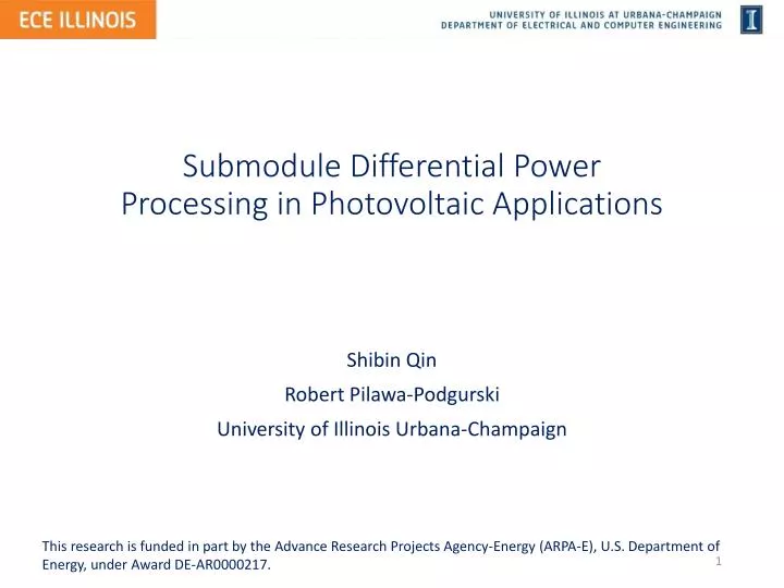
Submodule Differential Power Processing in Photovoltaic Applications. Shibin Qin Robert Pilawa-Podgurski University of Illinois Urbana-Champaign. This research is funded in part by the Advance Research Projects Agency-Energy (ARPA-E), U.S . Department of Energy, under Award DE-AR0000217. .

E N D
Submodule Differential Power Processing in Photovoltaic Applications Shibin Qin Robert Pilawa-Podgurski University of Illinois Urbana-Champaign This research is funded in part by the Advance Research Projects Agency-Energy (ARPA-E), U.S. Department of Energy, under Award DE-AR0000217.
Outline • Introduction • PV characteristic mismatch problem • Distributed power electronics • Differential power processing (DPP) • Control • Maximum power point tracking in DPP • The centralize approach • The distributed approach • Hardware Implementation • Experimental Testbed
PV Module • 1 • 2 • 3 • Each PV module consists of 3 submodules • PV modules (submodules) are connected in series for voltage stacking Current To the grid Central inverter
PV Module Mismatch • PV characteristic mismatch • Partial shading • Manufacturing variations • Non-uniform aging • Maximum power point tracking (MPPT) at submodule level Current To the grid Central inverter
Sub-module Level MPPT Solutions • Sub-module micro-inverter is prohibitive due to cost • DC optimizer has to process the full power of each sub-module Sub-module micro-inverter R. Pilawa-Podgurski, D. Perreault, Sub-Module Integrated Distributed Maximum Power Point Tracking for Solar Photovoltaic Applications , IEEE TPELS, June 2013
Differential Power Processing (DPP) • DPP converters process only the differential power • DPP is advantageous over DC optimizer in terms of system efficiency, converter power rating and ease of integration into existing design DPP system P. Shenoy, K. Kim, B. Johnson, and P. Krein, Differential power processing for increased energy production and reliability of photovoltaic systems, IEEE TPELS, June 2013
System Efficiency and Power Rating DC optimizer DPP
Ease of Integration and Scaling DC optimizer DPP
Outline • Introduction • PV characteristic mismatch problem • Distributed power electronics • Differential power processing (DPP) • Control • Maximum power point tracking in DPP • The centralize approach • The distributed approach • Hardware Implementation • Experimental Testbed
Maximum Power Point Tracking MPP at 100% irradiance Power [W] MPP at 80% irradiance MPP at 50% irradiance Current [A] • MPPT algorithm: find () such that each sub-module operates at their MPP point ,
Two Loop Control D1 D2 • for given • Separation of two control loop • Slow loop: inverter • Fast loop: DPP converters
The Centralized Approach DPPs Maximize Inverter updates Converter operation timeline • DPP control objective: • Slow loop: inverter • Fast loop: DPP converters
The Centralized Approach Real-time power input to the micro-inverter PV module characteristics • Micro-inverter trapped by local maximum before DPP turned on • DPP smoothed out the P-V curve and improved power output
The Distributed Approach • Requiring no local current sensing • Requiring only local voltage measurement and neighbor-to-neighbor communication
The Distributed Approach • 3-submodule, 2-DPP system, • insolation profile:100%,80%,50%
Outline • Introduction • PV characteristic mismatch problem • Distributed power electronics • Differential power processing (DPP) • Control • Maximum power point tracking in DPP • The centralize approach • The distributed approach • Hardware Implementation • Experimental Testbed
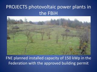
PV Junction Box Integration • Separate enclosure represents a significant cost
Hardware Implementation • Small passive component due to high switching frequency • No separate enclosure necessary for distributed power electronics • Converter peak efficiency above 95%
Outline • Introduction • PV characteristic mismatch problem • Distributed power electronics • Differential power processing (DPP) • Control • Maximum power point tracking in DPP • The centralize approach • The distributed approach • Hardware Implementation • Experimental Testbed
Solar Emulation • Controllable and repeatable indoor solar experiments • Preserving the dynamics of a true PV module
Field Test Illinois Center for a Smarter Electric Grid • Ongoing field test to verify the proposed technology in real irradiance • Tests including MPPT tracking efficiency, system reliability, etc.
Concluding Remarks • DPP Architecture • Low power rating • High system efficiency • High reliability • Easy to integrate • DPP MPPT Control: • Centralized and distributed solutions • Minimum communication • No local current sensing • True MPPT • Hardware Implementation • Small footprint, junction box integration • High converter efficiency • Experimental Testbed • Good experimental platform • Ready to support more solar research
Questions Questions? • Contact: Shibin Qin(sqin3@illinois.edu)
Acknowledgement • This research is funded in part by the Advance Research Projects Agency-Energy (ARPA-E), U.S. Department of Energy, under Award DE-AR0000217.
Sensing Small Current Change • Direct signal scaling • Moving window C. Barth, R. Pilawa-Podgurski, Dithering Digital Ripple Correlation Control with Digitally-Assisted Windowed Sensing for Solar Photovoltaic MPPT (Thursday 4:10pm, Session T34) Figure credit: Christopher Barth
Experimental Setup • PV module: SolarworldSunmodule® 235 Poly • Micro-inverter: Solarbridge Pantheon® II S. Qin, K. Kim, R. Pilawa-Podgurski, Laboratory emulation of a photovoltaic module for controllable insolation and realistic dynamic performance (PECI 2013)
Sensing Small Current Change • Signal amplification is limited by DC current value • Example: • DC current: • Current change: • ADC range: • Subtract DC value, amplify only AC value Module Current Bias point shift C. Barth, R. Pilawa-Podgurski, Dithering Digital Ripple Correlation Control with Digitally-Assisted Windowed Sensing for Solar Photovoltaic MPPT (Thursday, Session T34) Figure credit: Christopher Barth
Current Sensing Circuit • : scaled full current signal (DC+AC) • : DC bias provided by -controller PWM • : • Remove most of the DC component • Further amplify AC component • -controller adjusts to center in ADC range
DPP MPPT Algorithm: States • DPP converter states: • Converter 1 acquires ,through neighbor-neighbor communication, and vice versa
DPP MPPT Algorithm: Input • is maximized when: • Define: • Input:
DPP MPPT Algorithm: Update • Update function:
Experimental Result • DPP converters' duty ratios converges from non-optimal initial values • Duty ratio changes after every micro-inverter MPPT perturbation
Experimental Result • PV module power loss: sum of sub-module maximum power minus micro-inverter input power • PV module power loss includes: • tracking losses • DPP converter losses • but does not include: • conversion loss in the micro-inverter