Download
1 / 27
270 likes | 406 Vues
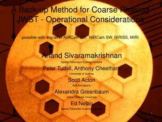
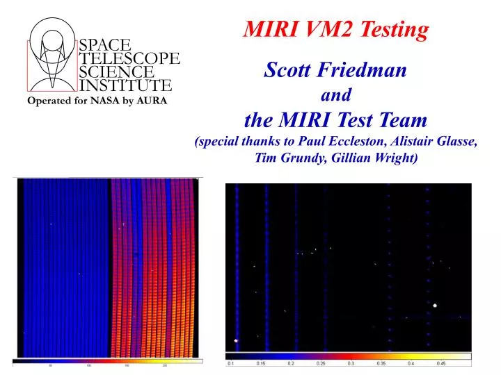
SPACE TELESCOPE SCIENCE INSTITUTE. Operated for NASA by AURA. MIRI VM2 Testing Scott Friedman and the MIRI Test Team (special thanks to Paul Eccleston, Alistair Glasse, Tim Grundy, Gillian Wright). The MIRI Instrument. MIRI Capabilities. Imaging = 5–27 microns

E N D
SPACE TELESCOPE SCIENCE INSTITUTE Operated for NASA by AURA MIRI VM2 TestingScott Friedmanandthe MIRI Test Team(special thanks to Paul Eccleston, Alistair Glasse,Tim Grundy, Gillian Wright)
The MIRI Instrument TIPS – 16 October 2008
MIRI Capabilities • Imaging • = 5–27 microns • 1.25 1.88 arcmin field of view • Low resolution spectrograph, R~100, 5-10 microns • Three 4–quadrant phase mask coronagraphs, one Lyot coronagraph • Medium resolution spectroscopy • = 5-27 microns (goal is 28.3 microns) • Integral field spectroscopy, 3.5 3.5 arcsec FOV (or more) • R ~ 3000–1000 from = 5–27 microns • NASA/JPL partnership with 10 country European Consortium sponsored by ESA • NASA provides focal planes and electronics. EC provides optics and bench. TIPS – 16 October 2008
MIRI Allocation 4QPM 15.5µm MIRIM FOV 4QPM 11.4µm Imager 4QPM 10.65µm Lyot Mask 23mm Low Resolution Spectrometer Medium Resolution Spectrometer MIRI Field of View TIPS – 16 October 2008
Spectral Format of MRS TIPS – 16 October 2008
MRS Spectral Bands C B A TIPS – 16 October 2008
Some Background • Several MIRI models • Structural-thermal model (STM) • Verification model (VM) • Flight model (FM) • Delays in MIRI Telescope Simulator (MTS) prompted testing split into two campaigns, VM1 & VM2 • VM1 • “MTS-lite” provided point source on imager • Provided testbed for thermal models, scripts, procedures, etc. • Cold testing from 12/17/07 – 1/28/08 • VM2 • Instrument cold from 8/16/08 – 10/2/08 • STScI shift support from Burns, Chen, Cracraft, Gordon, Friedman • Script testing by Robinson TIPS – 16 October 2008
MIRI Telescope Simulator (MTS) • MTS Objective • Deliver a test beam to MIRI similar to output beam of JWST with similar conditions to the flight environment • MTS Functionalities • Provide scanning point source across MIRI FOV • Provide extended source covering MIRI FOV • For both point and extended sources • Selectable source blackbody temperature and flux level • Provide linearly polarized source • Capability to adjust temperature of one element • Background level variation • Provide input pupil sampling by scanning broadband source • MTS is an instrument: 150 kg, 8 mechanisms, 4 etalons, WFE < /20 @ 5 m… TIPS – 16 October 2008
MIRI Telescope Simulator (MTS) Built by Instituto Nacianal de Técnica Aerospacial (INTA), Spain TIPS – 16 October 2008
MTS Cold Functional Test Summary • Heaters all fully operational • Cooldown heaters caused higher background, so heaters off during most of testing • MTS very dark when cold • Blackbody source very stable • Filter wheel and Variable Aperture Source fully operational • Source Scanning and Selection mechanism operational • Point source movable around entire FOV • Point source can be focused only over central region of imager • Point source flux level at MRS is low (~10 electrons/pixel/second at 700K) • Problem with linear stage of extended source - cannot illuminate MRS • Pupil scan system fully operational • Fold mirror system system almost fully operational • Range of motion limited for 1 of 2 mirrors. TIPS – 16 October 2008
IMG_OPT_01 FOV Measurement IMG_OPT_02 PSF Measurement IMG_OPT_03 Pupil Scanning IMG_OPT_04 Opto-Mechanical Stability IMG_OPT_05 Polarization IMG_OPT_06 Out-of-Field Stray Light IMG_RAD_01 Dark Behavior IMG_RAD_02 Nominal Background Behavior IMG_RAD_03 High Background Behavior IMG_RAD_04 Photometric Response To A Point Source IMG_RAD_05 Photometric Response To An Extended Source IMG_RAD_06 Imager Linearity IMG_RAD_07 Spectrophotometric Performance IMG_RAD_08 Photometric Stability IMG_RAD_09 Out of Band Radiation Sensitivity IMG_RAD_10 Imager Readout Modes IMG_RAD_11 Imager Calibrator Setup IMG_RAD_12 Latents IMG_RAD_13 Detector Settling COR_OPT_01 PSF Measurement and Rejection factor COR_OPT_02 Pupil Scanning COR_OPT_03 Opto-Mechanical Stability COR_OPT_04 Coronagraph Polarization COR_OPT_05 Coronagraph Peakup COR_RAD_01 Dark Behavior COR_RAD_02 Nominal Background Behavior COR_RAD_03 Photometric Response to a Point Source and Linearity COR_RAD_04 Spectrophotometric Performance COR_RAD_05 Out Of Band Radiation Sensitivity LRS_OPT_01 FOV Measurement LRS_OPT_02 Polarization LRS_OPT_03 Slit Width LRS_OPT_04 Spectral Resolution LRS_OPT_05 Wavelength Characterization LRS_OPT_06 Wavelength Registration LRS_OPT_07 Wavelength Stability LRS_OPT_08 Source Centering LRS_RAD_01 Dark Behavior LRS_RAD_02 Nominal Background Behavior LRS_RAD_03 Spectrophotometric Performance LRS_RAD_04 Linearity LRS_RAD_05 Photometric Stability LRS_RAD_06 Passband Characterization LRS_RAD_07 Out Of Band Radiation Sensitivity MRS_OPT_01 FOV Measurement MRS_OPT_02 PSF Measurement MRS_OPT_03 Pupil Scanning MRS_OPT_04 Opto-Mechanical Stability MRS_OPT_05 MRS Polarization MRS_OPT_06 Slice Width MRS_OPT_07 Spectral Resolution MRS_OPT_08 Wavelength Characterization MRS_OPT_09 Wavelength Stability MRS_OPT_10 Source Centering MRS_RAD_01 Dark Behavior MRS_RAD_02 Nominal Background Behavior MRS_RAD_03 High Background Behavior MRS_RAD_04 Spectrophotometric Performance MRS_RAD_05 MRS Linearity MRS_RAD_06 Slope Stability MRS_RAD_07 Photometric Stability MRS_RAD_08 Out Of Band Radiation Sensitivity MRS_RAD_09 Passband Characterization MRS_RAD_10 MRS Readout Modes MRS_RAD_11 MRS Calibrator Setup MRS_RAD_12 Latents MRS_RAD_13 Detector Settling VM2 Test Suite TIPS – 16 October 2008
Extended Source • Slope image • 11 micron filter • TBB = 300 K • Tint = 90 sec • Excellent flatness (in most regions) TIPS – 16 October 2008
Extended Source Flatness 90% of pixels in this region are within 2.8% of median pixel value. Courtesy of Alistair Glasse TIPS – 16 October 2008
Opening of Extended Source TIPS – 16 October 2008
Point Source MTS Focus Sweep TIPS – 16 October 2008
Zemax Ray Trace Model ofPoint Source Focus Sweep Courtesy of Martyn Wells TIPS – 16 October 2008
Region of Sharp Focus TIPS – 16 October 2008
Point Source Image from VM1 PSF width and size of Airy ring just as predicted by modeling. Conclusion: the VM is in focus. Problems with VM2 focusing are within the MTS. TIPS – 16 October 2008
MRS Internal Flat Field spatial • Sub-channel B • Slope image • 3 dark slices due to intentionally reduced pupils spectral Image Slicer TIPS – 16 October 2008
MTS Continuum Point Source on MRS TIPS – 16 October 2008
Etalon Point Source on MRS Full frame image Close-up TIPS – 16 October 2008
Etalon Point Source on MRS • Point source out of focus on MRS • FWHM ~ 2.5 pixels • Image not flat-fielded Courtesy of Rafael Martinez Galarza TIPS – 16 October 2008
Point Source Dark and Background Levels 7 microns CCC open CCC closed TIPS – 16 October 2008
Point Source Background Level25 microns • Scattered light from MTS scanning system structure • Background much lower than in VM1 due to colder MTS operating temperature TIPS – 16 October 2008
Cosmic Rays Cosmic Ray Hits Typical jump 500 - 3000 electrons TIPS – 16 October 2008
Conclusions (directly from Paul Eccleston) • Highly sensitive instrument is working properly in a representative environment • MTS is largely functioning very well except for point source focus and extended source illumination • Test plans mostly working well • When VM2 is complete (it is now) we will have thoroughly tested the VM and have met ALL objectives of the test programme. TIPS – 16 October 2008
Addendum • MIRI operations scripts • Controlled 4 mechanisms • Imager filter wheel • Both MRS grating/dichroic wheels • Contamination control cover • Run on warm VM by M. Robinson on 10/13/08 • All scripts ran to completion. No errors of any kind generated. • VM scheduled to be brought up to air today. TIPS – 16 October 2008