Download
1 / 50
540 likes | 1.05k Vues
Pulse Width Modulation. A Student Presentation By: Wayne Maxwell Martin Cacan Christopher Haile. Presentation Roadmap. Introduction and Background Applicable Definitions Pulse Width Modulation Duty Cycle Advantages/Disadvantages PWM Types Methods of PWM Generation Applications

E N D
Pulse Width Modulation A Student Presentation By: Wayne Maxwell Martin Cacan Christopher Haile
Presentation Roadmap • Introduction and Background • Applicable Definitions • Pulse Width Modulation • Duty Cycle • Advantages/Disadvantages • PWM Types • Methods of PWM Generation • Applications • Choosing the PWM Frequency • Implementation of PWM on the HCS12
Wayne Maxwell Presents • Introduction and Background • Applicable Definitions • Pulse Width Modulation • Duty Cycle • Advantages/Disadvantages • PWM Types • Methods of PWM Generation • Applications • Choosing the PWM Frequency • Implementation of PWM on the HCS12
A Brief History of Variable Power Devices To fulfill partial power requirements, variable resistance devices such as rheostats were used to control the current entering a device (i.e. sewing machines) These devices suffered from major energy losses from heat in the resistor elements. Other device power control devices included voltage stepping autotransformers such as the Autrastat. There was a need for a low cost, efficient,and compact option for providing adjustable power for electronic devices.
History of PWM Use Variable (Switching) power supplies began being used in mass by the military Commercial product designers became curious when seeing the military applications of the switching power supplies One of the early applications of Pulse Width Modulation was in the Sinclair X10, an audio amplifier in the 1960s In 1976, Bob Mammano (Silicon General) invented the SG1524 regulating pulse width modulator integrated circuit. Other companies soon followed leading to the evolution of PWM techniques. “Switching regulators are in the process of revolutionizing the power supply industry because of their low internal losses, small size and weight, and costs competitive with conventional series-pass or linear power supplies” -Abraham Pressman-
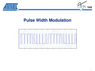
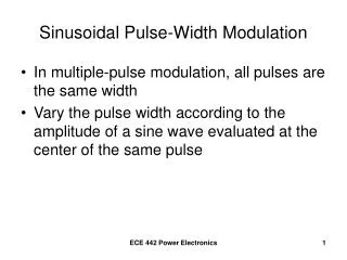
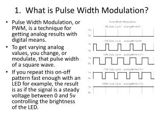
What is PWM? Definition: Pulse Width Modulation is a technique that conforms a signal width, generally pulses based on modulator signal information. The general purpose of Pulse Width Modulation is to control power delivery, especially to inertial electrical devices. The on-off behavior changes the average power of signal. Output signal alternates between on and off within a specified period. If signal toggles between on and off quicker than the load, then the load is not affected by the toggling. A secondary use of PWM is to encode information for transmission.
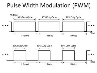
Duty Cycle Definition: The Duty Cycle is a measure of the time the modulated signal is in its “high” state. It is generally recorded as the percentage of the signal period where the signal is considered on. On Off VH Duty Cycle (D) VL Period (T)
Duty Cycle Formulation On Off VH Duty Cycle (D) VL Period (T) • Duty Cycle is determined by: • *Average value of a signal can be found as: • *In general analysis, VL is taken as zero volts for simplicity.
Advantages of Using PWM Average value proportional to duty cycle, this dependence is often observed to follow a linear trend due to the previous formulaic definition. Low power used in transistors used to switch the signal, and fast switching possible due to MOSFETS and power transistors at speeds in excess of 100 kHz Alleviates the problem of high heat loses through resistive elements at intermediate voltage points
Disadvantages to Using PWM Cost of integrated circuit packages for PWM Complexity of circuitry necessary for implementation Radio Frequency Interference/Electromagnetic Interference limits the performance of the circuitry Voltage spikes in the pulse signal to a rapid succession of switches similar to an impulse
General Types of Pulse Width Modulation There are three commonly used types of PWM defined by which edge of the analog signal is to be modulated Lead Edge Modulation Trail Edge Modulation Pulse Center Two Edge Modulation/Phase Correct PWM
Lead Edge Modulation The lead edge of the trigger signal is fixed to the leading edge of the time spectrum and the trailing edge is modulated Trigger Signal PWM Signal
Methods for Pulse Width Modulation Generation There are several methods for generating the PWM signal, including the following: Analog Generation Methods The Intersective Method Digital Generation Method Delta Modulation Delta Sigma Modulation Space Vector Modulation Application Specific Methods Direct Torque Control Time Proportioning
Analog Generation Methods The Intersective Method: Allows for the analog creation of the PWM signal through simply noting the intersections between a sawtooth or triangular trigger signal and a reference sinusoid.
Digital Generation Methods Delta Modulation: By using the reference analog signal only, a set of limits set by a constant offset, and the integrated PWM signal, a switching method is created.
Digital Generation Methods Delta-Sigma Modulation: Similar to the Delta Modulation method in that it involves an integral. However, an error signal is developed by subtracting the PWM signal from a reference sinusoid and then integrated. When this integrated error signal reaches a set of defined limits, the PWM signal will switch modes. Analog Signal Integrated Error 1: Error (AS-PWM) 2: PWM Signal
Martin Cacan Presents • Introduction and Background • Applicable Definitions • Pulse Width Modulation • Duty Cycle • Advantages/Disadvantages • PWM Types • Methods of PWM Generation • Applications • Choosing the PWM Frequency • Implementation of PWM on the HCS12
Applications • Audio and video effects • Telecommunications • Power delivery • Voltage regulation • Amplification • Controlling Actuators • Use as ADC
Applications • Audio and video effects • Telecommunications • Power delivery • Voltage regulation • Amplification • Controlling Actuators • Use as ADC
Applications: LED Displays • RGB LEDs often use 8 bit PWM control • Each pixel is individually controlled • Color can be defined as % of duty cycle (#/255) • Red: 0 – 255 • Green: 0 – 255 • Blue: 0 – 255 • Number of colors: 256^3 = 16.77 million • Decimal Code (RR,GG,BB) • Hex Code #RRGGBB
Applications: LED Displays TPWM (RR,GG,BB) (128,255,65)
Applications: LED Displays • How to get a color code? • Use online color mapping tool: • MATLAB! http://www.rapidtables.com/web/color/RGB_Color.htm N N BLUE M A = imread(…); A = GREEN M RED
Applications: Telecommunications • Embed a data signal in a modified clock signal • Can discretize further for larger than base 2 transmission Clock: @ 50% duty cycle 1: Extends duty cycle 0: Shortens duty cycle
Application: Voltage Regulator • DC voltage can be regulated by PWM to modify output voltage • 12v supply controlled by PWM at 50% duty cycle can create an output signal of 6v • Use smoothing filters to get DC output • Can use feedback control to monitor output voltage and change duty cycle to ensure consistent output given varying input or load
Application: Voltage Regulator • What’s the difference between a voltage regulator and a voltage divider (linear regulator)?
Application: Voltage Regulator • What’s the difference between a voltage regulator and a voltage divider (linear regulator)? • Linear regulators suffer from power dissipation proportional to the output current • High current also implies Ohmic Heating of elements • Efficiency of linear regulator: ~50% • Efficiency of a PWM voltage regulator: ~90%
Choosing a PWM Frequency • Basic considerations: • Transitions can only occur on a clock tick • Frequency limited by your clock and desired resolution • Resolution is defined by clock speed and frequency of the PWM • The faster you run the PWM, the fewer clock ticks occur in the period considered lower duty cycle resolution
Choosing a PWM Frequency • Many actuators can be modeled as a first or second order filter (e.g. motors, servos) A frequency in this region can excite the system! A PWM frequency is rejected by the system
Choosing a PWM frequency Input PWM Signal Response of 2nd order system 30
Christopher Haile Presents • Introduction and Background • Applicable Definitions • Pulse Width Modulation • Duty Cycle • Advantages/Disadvantages • PWM Types • Methods of PWM Generation • Applications • Choosing the PWM Frequency • Implementation of PWM on the HCS12
Implementation • PWM8B6C dedicated chip • Signal outputted through port P
PWM8B6C Module • 6 Independent 8-bit channels • Can be concatenated to 3 • 16-bit channels • Independently adjustable polarity, clock, alignment, duty cycle, and period • Dedicated counter for each channel
Features • 3 Modes of Operation • Normal: everything is available • Wait: Low-power consumption and clock disabled • Freeze: Option to disable input clock • Four source clocks • A, SA, B, SB • Emergency shutdown • Some changes take a complete cycle to be implemented
Memory Map • Configured through specific registers • Base address is defined at the MCU level • Address offset is defined at the module level • Register address = base address + address offset • Registers are located from $00E0 - $00FF
PWM Enable Register (PWME) Located at $00E0 Set PWME “x” 0: to disable PWM channel “x” 1: to enable PWM channel “x” Chanel is activated when bit is set If 16-bit resolution is used, then PWME4/2/0 are disabled
PWM Polarity Register (PWMPOL) Located at $00E1 Set PPOLx to 0: output channel starts low and moves to high when duty cycle is reached 1: output channel starts high and moves to low when duty cycle is reached
PWM Clock Select Register (PWMCLK) PWMCLK is located at $00E2 Set PCLK5, PCLK4, PCLK1, PCLK0 to 0 to use Clock A 1 to use Clock SA Set PCLK3, PCLK2 to 0 to use Clock B 1 to use Clock SB
PWM Prescaler Register (PWMPRCLK) Located at $00E3 Used to prescale clocks A and B
PWM Scale A Register (PWMSCLA) Located at $00E8 Scale value used in scaling Clock A to generate Clock SA Store a hexadecimal value in order to change the clock frequency of SA Note: When PWMSCLA = $00, PWMSCLA value is considered a full scale value of 256.
Located at $00E9 Scale value used in scaling Clock B to generate Clock SB Store a hexadecimal value in order to change the clock frequency of SB Note: When PWMSCLA = $00, PWMSCLA value is considered a full scale value of 256. PWM Scale B Register (PWMSCLB) PWM Scale B Register (PWMSCLB)
PWM Counter Register (PWMCNTx) Six 8-bit counters located at $00EC - $00F1 One up/down counter per channel, can be read and written to In left aligned mode, the counter counts from 0 to the value in the period register-1. In center aligned mode, the counter counts from zero to the value in the period register-1 and then back down to zero. Any write to the register causes the value to be reset to #$00 and the counting procedure is restarted.
PWM Center Align Register (PWMCAE) Located at $00E4 Set CAEx to 0: for left align output signal 1: for center align output signal Note: can only be set when channel is disabled
PWM Control Register (PWMCTL) Located at $00E5 Set CONxyto 0: to keep PWM channels separate (8-bit) 1: to concatenate PWM channels x and y together (16-bit) Channel y determines the configuration x becomes the high byte and y becomes the low byte Bits PSWAI and PFRZ set either wait or freeze mode Note: Changes only occur when channels are disabled
PWM Period Register (PWMPERx) Six Period Registers located at $00F2 - $00F7 Determine the PWM period Changes occur when: Current period ends Counter is written to Channel is disabled Left-Aligned: Center-Aligned:
PWM Resolution PWM Resolution • The true resolution depends on the value in PWMPERx even though the PWM module is said to be 8-bit. • The number of distinct duty cycles equals the value stored in PWMPERx. • Maximum number of distinct duty cycles is achieved by writing $FF to the register PWMPERx so that it can represent 256 duty cycle states (00, 01, 02, …, to FF), which corresponds to 28=256 resolution.
PWM Duty Register (PWMDTYx) • (6) Duty Registers located at $00F8 - $00FD • Determines the duty of the associated PWM channel • Changes occur when: • Current period ends • Counter written to • Channel is disabled Polarity = 0: Polarity = 1:
PWM Shutdown Register (PWMSDN) • Located at $00FE • PWMENA: Enables and disables emergency shut down • PWMIF (Interrupt flag): Set when an input is detected in pin 5 • PWMIE (Interrupt Enable): Enables and disables CPU interrupts • PWMRSTRT: Resets the counters • PWMLVL (Shutdown Output Level): Determines if output is high or low when shutdown • PWM5IN (Input Status): Reflects status of pin 5 • PWM5INL: Determines active level of pin 5
Assembly Code PWME EQU $00E0 PWMPOL EQU $00E1 PWMCLK EQU $00E2 PWMPRCLK EQU $00E3 PWMCAE EQU $00E4 PWMCTL EQU $00E5 PWMPER1 EQU $00F3 PWMDTY1 EQU $00F9 ORG $1000 LDAA #$00 STAA PWMCLK ; Sets source clocks to clock A STAA PWMPOL ; The signal goes from low to high STAA PWMCTL ; Makes all channels 8-bit STAA PWMCAE ; Signals are left aligned LDAA #$FA STAA PWMPER1 ; Sets the period to 250 clock cycles LDAA #$AF STAA PWMDTY1 ; Makes the duty cycle equal to 30% LDAA #$02 STAA PWMPRCLK ; Sets the prescaler to 4 STAA PMWE ; Enables and starts channel 1 ……
QUESTIONS? References: • www.rapidtables.com/web/color/RGB_Color.htm • http://www.mathworks.com/help/matlab/ref/imread.html • http://en.wikipedia.org/wiki/Pulse-width_modulation#Telecommunications • http://www.analog.com/en/content/ta_fundamentals_of_voltage_regulators/fca.html • http://www.monkeylectric.com • http://en.wikipedia.org/wiki/Pulse-width_modulation • http://tutorial.cytron.com.my/2012/01/14/basic-pulse-width-modulation-pwm/ • http://www.societyofrobots.com/member_tutorials/book/export/html/228 • http://powerelectronics.com/power-management/pwm-single-chip-giant-industry • http://www.freescale.com/files/microcontrollers/doc/data_sheet/MC9S12C128V1.pdf