Download

1 / 5
700 likes | 2.9k Vues
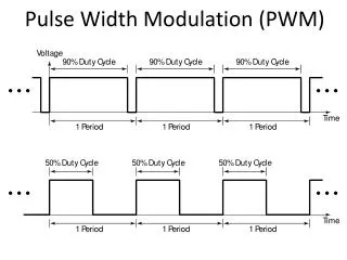
1. What is Pulse Width Modulation ?. Pulse Width Modulation, or PWM, is a technique for getting analog results with digital means. To get varying analog values, you change, or modulate, that pulse width of a square wave.

E N D
1. What is Pulse Width Modulation? • Pulse Width Modulation, or PWM, is a technique for getting analog results with digital means. • To get varying analog values, you change, or modulate, that pulse width of a square wave. • If you repeat this on-off pattern fast enough with an LED for example, the result is as if the signal is a steady voltage between 0 and 5v controlling the brightness of the LED.
2. How is pulse width modulation used in the headlight circuit? • During the daytime we use a duty cycle of 50% or less by writing 127 or less to the PWM ports use for the LED’s. • During the night we can use a duty cycle of 100% by writing 255 to the output PWM ports.
3. What is Debouncing? • Bouncing is the tendency of any two metal contacts in an electronic device to generate multiple signals as the contacts close or open. • Debouncingis any kind of hardware device or software that ensures that only a single signal will be acted upon for a single opening or closing of a contact.
4. How does a Flex Sensor work? • One side of the sensor is printed with a polymer ink that has conductive particles embedded in it. • When the sensor is straight, the particles give the ink a lower resistance. • When the sensor is bent away from the ink, the conductive particles move further apart, increasing this resistance.
5. Supposed that you were required to add a temperature sensor to your circuit so that a yellow LED flashed if the temperature of the engine oil was too high. What circuit components would need to be added to the breadboard to achieve this? Answer: Thermister, 10kW Resistor, LED, and 330W Resistor (b) Describe which pins of the Arduino could be used for these additional components. Write you answer in such a way that anyone with some experience in the electronics lab could construct the circuit. Answer (From the portfolio): The thermister would be connected in series with the 10kW resistor between GND and +5V. Connect pin A3 (for example) of the Arduino to the junction between the 10kW resistor and thermister. The LED would be connected in series with the 330Wresistor between pin 2 (for example) and GND.