Download
1 / 11
120 likes | 285 Vues
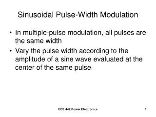
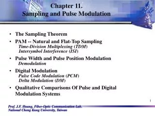
Introduction to PWMs (Pulse Width Modulation) Motor Speed Control. In many instances it is not desirable to have a motor run at full speed. Pulse Width Modulation. What is PWM?. PWM stands for Pulse Width Modulation PWM controllers switch the motor on and off in a series of pulses.

E N D
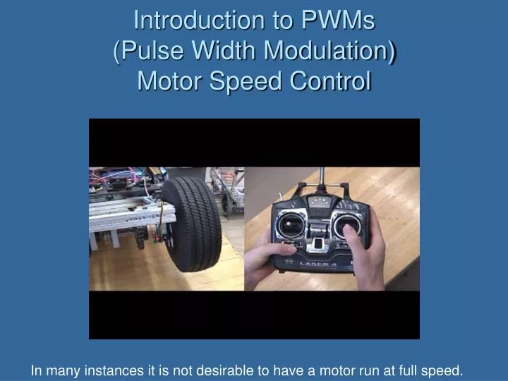
Introduction to PWMs(Pulse Width Modulation)Motor Speed Control In many instances it is not desirable to have a motor run at full speed.
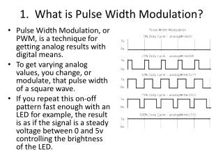
What is PWM? • PWM stands for Pulse Width Modulation • PWM controllers switch the motor on and off in a series of pulses. • Modulate means to adjust or regulate. A PWM sends a signal that regulates the motor- hence Pulse Width Modulation.
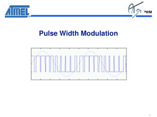
How Do You See PWM ? The video below shows the waveform and driven motor Note: Motor does not begin moving until the power level is increased enough to overcome the friction of the drive train.
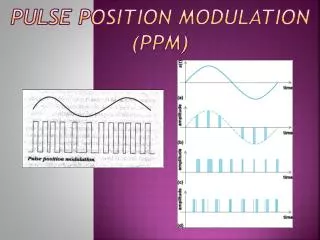
Designates motor ON Pictures of the Waveform? • A. The motor is on for most of the time and only off a short while, so the speed is near maximum • B. The switch is on 50% and off 50%. • C. The motor will only rotate slowly.
Designates motor ON High Speed Signal • The signal at the right shows the motor on for most of the time, the white dips indicate when the motor isn’t receiving power.
Signal on Signal on Signal on Signal off Signal off
Designates motor ON Signal With The Motor Half Speed • The signal at the right shows the motor receiving power half the time.
Designates motor ON Low Speed Signal • The signal at the right shows the low speed signal which turns the motor slowly.
Switch Motor Schematic of a Manually operated PWM Low Speed Circuit
Manual Low Speed PWM Generation Touch Controlled Switch