Download
1 / 27
450 likes | 872 Vues
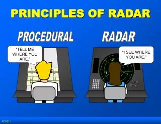
Principles of Radar. General information. Range ( Distance from own ship) Bearing (Angle from own ship’s heading) ARPA ( A utomatic R adar P lotting A id) - Collision Avoidance. ARPA tells us what other vessels are doing How does the radar see other vessels in rain and sea clutter

E N D
Principles of Radar General information
Range (Distance from own ship) Bearing (Angle from own ship’s heading) ARPA (Automatic Radar Plotting Aid) - Collision Avoidance. ARPA tells us what other vessels are doing How does the radar see other vessels in rain and sea clutter Main radar Components Factors affecting the performance of the radar Fundamentals
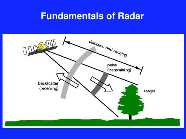
Transmitter – Provides a powerful source of microwaves – needed to achieve range performance Antenna- Focuses the microwaves into a narrow beam. The microwaves are reflected off targets (vessels, buoys, land etc.). Antenna – Collects the reflected microwaves from objects in its path. Receiver- detects and amplifies the received signals. Display Processor – removes the unwanted signals, e.g. clutter, but keeps those from targets and displays the results on the screen. How it works The Radar Energy is Pulsed at Up to 3000 Pulses Per Second
Imagine now just a pulse of microwave energy From the time each pulse is sent out - time how long it takes to receive a reflection from an object We know the speed of microwaves (300,000 km per sec) Distance travelled = time x speed Therefore: Range of target = half total distance travelled by pulse Range & Bearing • At any given moment the radar display knows the direction the antenna is pointing with respect to the ships head • Heading Marker pulse is sent from the top unit to the display once every antenna revolution • In addition 4096 bearing pulses are sent to the display for each revolution of the antenna time Radar Automatically Calculates Range and Bearing of the Target
ARPA – Automatic Radar Plotting Aid • We now know a target’s position (i.e. range and bearing) • A short time later we know its new position • The speed and direction of the target can be calculated • Therefore – it is possible to estimate where the target will be in say 5 minutes. • Also, we know our own speed and direction and … • where we will be in 5 minutes • If the two points coincide !!!! Collision Radar Automatically Calculates The Speed and Direction of all ARPA Targets and Those of Own Ship to Provide Important Anti Collision Information
What is Clutter? Unfortunately, radar pulses are also reflected from the sea. • It is most important that a radar should be effective at removing unwanted clutter, to show the targets • S-Band radars are typically 3 times better than X-band radars in suppressing clutter in heavy seas, where small targets are masked by water spray • Rain also produces clutter that can mask targets
What does Clutter look like? A typical radar return on diagram Distance region of rain Intensity of the return signal target target in rain targets in clutter sea clutter region Main ‘bang’ i.e. Pulse from Magnetron • Sea & Rain clutter can be processed in one of two ways: • Manual adjustment of Anti-clutter sea & rain • Automatic clutter rejection – known as Auto or Clearscan
How do we suppress Clutter? A typical radar return on diagram Distance Intensity of the return signal Anti-clutter sea waveform Waveform with clutter suppression Manual Clutter Suppression Anti-clutter sea generates a waveform that attempts to match the size and slope of the clutter return and is ‘subtracted’ from the original radar return.
Rain Clutter Suppression Using Manual Anti-Clutter Rain Suppression: Anti-Clutter Rain suppresses signals that are not changing much. As the control is increased, an increasing proportion of the signal is affected, revealing more of the target in the rain covered region. Distance Intensity of the return signal Increasing a/c rain
The Transmitter • The Transmitter transmits very short pulses of microwave energy. Typically 1µs (one microsecond) long pulse to 0.05µs short pulse. • Note that 0.05µs can also be written as 50ns (50 nano seconds) • In the transmitter, the source of the RF power is the magnetron, which is switched on and off at a fast rate by the modulator, which controls both pulse width and pulse repetition frequency (prf). • The average power of a radar transmitter is the product of Peak Power x PRF x Pulse Width. • eg, for VMFT 25kW operating at 1700Hz PRF and 0.05µs pulse width. • Average Power = 25000 x 1700 x .050 x 10-6 = 2W • It is the average power of the transmitter which influences the maximum range of the radar, not peak power. E.g. by increasing the average power of a radar by a factor of 2, the range will be increased by 20%.
Rotating Antenna • A rotating antenna which produces a fan-shaped beam. The height of the fan is the vertical beamwidth, typically 25°, Marine radar must have vertical beam width of at least 20° to take into account the rolling motion of the ship • Every receiver generates noise (unwanted signal) and it is the level of this noise that the received signal must ‘overcome’ to be detected and displayed. E.g. by reducing the receiver noise by half, the radar range will be increase by 20% • The width of the fan is the horizontal beam width, typically 1-2°. The horizontal beam width determines the bearing resolution of the radar • Note: The range resolution of the radar is determined by the pulse width of the transmitted pulse. Short pulse can display more detail at short ranges, but longer pulses are required for good long range performance • The narrower the horizontal and vertical beam width, the greater the transmitted power focussed on the target and also the greater the received power is reflected back to the antenna
+ | 2° Beamwidth | + 4ft Beamwidth defined at ½ power level Relationship Between Antenna Size and Beam Width Analogy to Light Antenna LIGHT BULB Radiates in virtually all directions. ISOTROPIC Radiates in all directions equally. Example: Antenna in a mobile phone is approximately isotropic. - it radiates in virtually all directions SHORT ANTENNA Example: 4ft X-Band antenna - wide beamwidth SMALL DEVICE Example: Torch - wide beamwidth LONG ANTENNA Example: 8ft X-Band antenna - narrow beamwidth LARGE DEVICE Example: Searchlight - narrow beamwidth + 1° Beamwidth + 8ft Beamwidth defined at ½ power level
Microwave energy from magnetron fills waveguide Waveguide Antenna Case Metal Guide Antenna Case Antenna Height 4 inches Vertical beam formed in this direction Horizontal beam formed in this direction Waveguide Antenna Length eg, 4ft, 6ft, 8ft, 9ft or 12ft Energy leaks from slots cut in waveguide Basic Marine Radar System –The Major Components Plain view Side view (X-Band Antenna) Horizontal beam width is narrow because antenna length is large. Vertical beam width is wide because antenna height is small.
The Receiver • A sensitive microwave receiver which must detect and amplify the very weak signals received by the antenne • Every receiver generates noise (unwanted signal) and it is the level of this noise that the received signal must ‘overcome’ to be detected and displayed. E.g. by reducing the receiver noise by half, the radar range will be increase by 20% • PULSE WIDTH: The shorter the pulse, the wider the transmitted bandwidth. The bandwidth of the receiver should be matched to the pulse width of the transmitter. Therefore the bandwidth of the receiver also plays an important part in the radar to produce the best signal to noise ratio • fore cannot judge Range Performance of a Radar by its ‘brochure’ Transmitter Power • On short pulse widths the bandwidth of the receiver is generally wide, eg for a 50ns pulse the option bandwidth is 20MHz, whereas for a 1µSec pulse, the option bandwidth is 1MHz
The Basic Radar Equation The maximum range performance of radar is given by: l a 2 2 P x PW x prf x G x x Range = (in metres) 4 1.2 p 3 NF x x TR x KT x Af x 4 L PW where P = Peak Power (Watts) PW = Transmitter Pulse Width in seconds prf = Pulse Repetition Frequency in Hz G = Antenna Gain in dB l = Transmission Wavelength in m a = Cross section area of target NF = Noise figure of the receiver in dB 1.2 = Ideal Bandwidth of the receiver as a function of pulse duration. PW TR = Two way transmission loss in waveguide, rotating joint etc in dB KT = Temperature of the thermal noise of the radar system (figure used is 4 x 10-21W/Hz) Af = Attenuation factor is space (rain, fog, snow, mist etc) in dB 2 L
What Does the Equation Mean? (1) Transmitter Power - Doubling the average transmitter power of a radar only gives a 20% greater range performance (assuming not horizon limited). Receiver Noise Figure - Halving the noise figure of the radar receiver by gives a 20% greater range performance (assuming not horizon limited). Antenna Beam width - Doubling the length of a radar antenna halves the horizontal beam width and gives a 40% greater range performance (assuming not horizon limited).
What Does the Equation Mean? (2) Rain - For small targets in rain of 4mm or 8mm per hour, the S-band Radar performance will be approximately 25% and 40% greater than that of the X-band radar. Waveguide Losses - The range performance of a radar will be reduced by about 25% when a 20m length of waveguide is used between the transceiver and scanner unit. -------------------------------------------------------------------------------------------------- Clear Weather - An X-band Radar on a calm sea and in absolute clear weather conditions free of moisture gives a 15% better range performance than an S-band Radar, all parameters being the same.
Add the Complication of the Curvature of the Earth Note: It is not possible to overcome the Radar Horizon effect, for example by improving the Radar. There is no actual benefit to be obtained by providing very long range scales on the Radar display, such as 96nm or greater.
What are ‘New Technology (solid state)’ Radars? • These radars use Solid State transmitters instead of Magnetrons • Magnetrons have a limited life, so require periodic replacement. Life of Solid-State devices in service not yet known, but potentially longer than Magnetrons • However, Solid State devices produce much less power than Magnetrons, therefore techniques must be used to produce equivalent range performance to Magnetrons • There are currently two techniques: 1) Pulse Doppler 2) FMCW (Frequency Modulated Continuous Wave)
Pulse Doppler Radar • As with Magnetron radars, Pulse Doppler radars transmit pulses, but the pulses are about 100 times longer than for Magnetrons, to compensate for the lower power of Solid State devices (about 100 times lower). • These pulses would be too long to allow small details to be shown on the display that mariners require. In other words, the range resolution would not be sufficient. • However, this problem is overcome by digitally processing the received pulses, to reduce their lengths. This is known as ‘Pulse Compression’.
Pulse Doppler Radar Doppler Effect • This is the effect that causes, for example, the siren of a fast-moving police car to apparently drop in frequency as it passes you. The fast motion of the vehicle ‘squeezes’ the waves from its siren as it approaches, and then ‘stretches’ the waves as it goes away. • It is possible to measure this effect with radar, but the transmitter must transmit a very pure and stable signal. Solid State transmitters can provide this, but Magnetron transmitters cannot. • The advantage of using Doppler, is that fast-moving targets in sea clutter can be more easily detected, because their speed (and therefore Doppler effect), is greater than the speed of the surrounding waves. • However, it should be noted that: • It is only speed directly towards or away from the radar that can be measured by Doppler. • This technique will not provide improvement (compared to Magnetron radars) for detection of slow-moving targets or important targets such as buoys and hazardous floating objects.
FMCW Radar • As its name would imply, Frequency Modulated Continuous Wave Radar transmits continuously and not in pulses. • Remember that pulsed radar gets range information by timing how long each pulse takes to return to the radar. • FMCW radars just vary the frequency of transmission (This is called Frequency Modulation). Reflections from targets return at different frequencies, depending on how long it took to do the round ‘trip’ from radar to target and back to radar. • The radar ‘knows’ exactly when it transmitted each frequency and can therefore calculate how long it took for that frequency to return. (Note: This is a very simplistic description, only used to explain the principle) • Because FMCW transmits continuously, it can use even lower transmit power than Solid State Pulse Doppler radars (typically 10 times lower).
Transmitted Power Comparisons • The Average power transmitted determines the Range Performance of a Radar • Average Power = Transmitter Power x Proportion of time Transmitter is switched on E.g. For BME S band, 30,000Watts x 0.06% = 19 Watts • Comparison of the three main Radar types, as follows:
Comparison of Magnetron and Solid State Radars • Magnetron Radars have much higher Transmitter Power than Solid State Radars, but Average Power transmitted is similar • Therefore cannot judge Range Performance of a Radar by its ‘brochure’ Transmitter Power • Solid State Radars transmit for much greater proportion of time than Magnetron Radars. Note: This characteristic of Solid State Radars may result in unacceptable interference to Magnetron Radars (and other Solid State Radars)
Mark pages according to the proprietary level of information as described in Company Procedure J103 (or remove)