Download
1 / 32
320 likes | 322 Vues
This presentation discusses the cross section measurement at the Large Hadron Collider (LHC), focusing on the use of totem detectors and high-beta optics. The aim of TOTEM is to achieve ~1% accuracy in cross section measurement. The presentation also covers the use of inelastic and elastic detectors, as well as the design considerations for Roman Pot detectors. Additionally, the use of 3D microstrip diodes for edgeless detectors is explored.

E N D
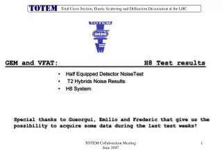
TOTEMTotal cross section measurement at LHC Marco Bozzo INFN Genova and Universita’ di Genova (Italy) On behalf of the Collaboration: Brunel, CERN, Cracow, Dresden, Genoa, Grenoble, Helsinki, Prague. http://totem.web.cern.ch/Totem/ LHC 2003- FNAL Workshop - May 2, 2003
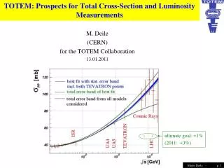
Dispersion relation fit (logs)g, g=2.20.3 • Current models predictions: 100-130mb • Aim of TOTEM: ~1% accuracy • Absolute calibration of Luminosity stot LHC 2003- FNAL Workshop - May 2, 2003
(i) “OPTICAL THEOREM” (ii) Luminosity Independent Method LHC 2003- FNAL Workshop - May 2, 2003
Large-t Elastic scattering Impact picture and Regge models LHC 2003- FNAL Workshop - May 2, 2003
Inelastic detectors (T1 and T2) in CMS Elastic detectors (RP’s) in the straight section LHC 2003- FNAL Workshop - May 2, 2003
Elastic scattering and High β optics • Cross section is large can be measured with relatively Low Luminosity ~ 1028 and short runs. • Low divergence beams require a special High- β optics. • For β=1100m beam angular spread at IP is 0.67 μrad and beam size is 0.74mm (rms). • Crossing angle of 150 μrad is not sufficient to avoid parasitic collisions need zero crossing angle: 36 bunches 1 out of 100 (time separation ~2.5 μsec or 740m) • to measure precisely the angle of scattered particles very close to the beam detectors placed at π/2 phase advance. • This results in a “parallel to point focus” optics where displacement correlates directly to the scattering angle • 2 such points exist in warm section • measure possible in Horizontal or Vertical plane. LHC 2003- FNAL Workshop - May 2, 2003
b* = 1100 m x = Leffq +vx0 v Leff(m) RP1 = 147m RP3=215m efficient as close as possible to the beam Acceptance: pots at same position and different inefficient edge of detectors Acceptance: track seen in either pot compared with single pot acceptance LHC 2003- FNAL Workshop - May 2, 2003
1037cm-2 Ldt=1033cm-2 elastic scattering b* =1100 m18 m 1 eff.day (105sec) L = 10281032 cm-2 sec-1 5x10³/GeV2 Max t b* =18 m Max t b* =1100 m ( M.Islam ) 15/GeV2 LHC 2003- FNAL Workshop - May 2, 2003
Roman Pot Window thickness 0.1 mm – First tests in 2002 LHC 2003- FNAL Workshop - May 2, 2003
~3cm Roman Pot detector 50 μ pitch Si strip detector CMS Hybrid Thermal analysis LHC 2003- FNAL Workshop - May 2, 2003
Detectors for elastic scattering Much effort to operate At the largest beta, closest to the beam (10 σ-beam ~ 0.5 mm), with reduced n. of bunches and emittance … Delicate part is the design of the detector region near the beam and the choice of the detector: The window, the mechanical tolerances, the inefficient region should be minimum • Standard silicon : 0.5 mm guard ring (typ.) • Silicon strip at LN2 temperature. Can work with efficiency up to the edge when edge is ‘cut’ (and properly treated). idea suggested by RD39 and NA60, tested on beam by TOTEM in 2002. • 3D detectors: edgeless and warm (S. Parker, C.Kenney), test of 1cm x 1cm detector with beam in summer 2003. LHC 2003- FNAL Workshop - May 2, 2003
3D Microstrip Diodes CMS Tracker Cold Silicon can be edgeless - tests 2002 Cut diode gives Pair of edgeless detectors (RD39 - Z.Li / BNL) Edge of ‘cut’ Silicon Strip Detector (50mm pitch) Microstrip Silicon Sensor (NA60 - Z.Li / BNL) LHC 2003- FNAL Workshop - May 2, 2003
P3 P7 Cut strip detector P4 P8 beam 15mm Edgeless diode pair 6 x 6, 0.4 mm gap 1.2mm P6 24 strips x 50mm (NA60) 140mm 140mm Cold Silicon Tests Results Silicon Microstrip Detectors Edgeless Silicon Diodes (RD39) 100 V bias 500 000 Events with tracks = 471 50 m from Survey = 435 35 m measured Sensitive edge coincides with survey within one strip ~ 0 ±30 mm LHC 2003- FNAL Workshop - May 2, 2003
Edgeless and warm : Si 3D Detectors S. Parker, C. Kenney 1995 New ‘3D’ TECHNOLOGY E-field line contained by edge (p) electrode SENSITIVE Within 10 mm of EDGE Side view • EDGE SENSITIVITY <10 mm • COLLECTION PATHS ~50 mm • SPATIAL RESOLUTION 10-15 mm • DEPLETION VOLTAGE < 10 V • SPEED AT RT 3.5 ns • SENSITIVE AREA 3X3 cm2 • SIGNAL AMPLITUDE 24 000 e before Irradiation • SIGNAL AMPLITUDE 15 000 e- at 1015n/cm2 50mm pitch Top view Pictures of processed structures Brunel, Hawaii, Stanford 2003 LHC 2003- FNAL Workshop - May 2, 2003
3D response to particles Brunel, CERN, Hawaii, Stanford Pulse height • Small bias 5-8 V • Speed 1.5, 3.5 ns • Radiation hardness MIP Ileak = 0.45 nA (average) 200 mm Ileak = 0.26 nA (average) 100 mm C = 0.2 pF per electrode MIP 1x10¹⁵ p/cm2 20oC LHC 2003- FNAL Workshop - May 2, 2003
Detector Secondary vacuum Beam vacuum Miniaturization of Roman pots • To approach beams in the horizontal direction, where space between the pipes is small, the detector movement might become smaller if put in “secondary” vacuum together with detectors. We are studying how to approcah beam “horizontally”. P beam LHC 2003- FNAL Workshop - May 2, 2003
Si-pad geometry (Sintef) Roman Pot Trigger • Silicon detector pad for trigger: 500 pads of 1mm2 • Trigger chip under study • Fast-or of 128 channels for fast trigger extraction • Multiplicity processor to reject multi-hit events • Timing precision about 1 nsec useful to identify by TOF the longitudinal position of interaction LHC 2003- FNAL Workshop - May 2, 2003
Elastic detectors • 100-150 small size (~4x4cm) silicon detectors necessary for entire experiment • No extreme requirements on radiation hardness . • Read out with CMS APV hybrid allows also easy integration in CMS DAQ for common runs. • Choice on final technology will be taken during 2004. LHC 2003- FNAL Workshop - May 2, 2003
The measurement of the inelastic rate • Needs fully inclusive “minimum bias” trigger with known efficiency • Identification of beam-beam events from background by reconstruction of interaction vertex • Two main event topologies • NSD ~85% of inelastic cross section • SD ~ 15% • Trigger combinations • Double arm for NSD (clean, low background) • Single arm for SD (beam gas int. looks like SD!) requiring signal in roman pot on opposite side can help in removing background • Simple detector telescopes in the forward region LHC 2003- FNAL Workshop - May 2, 2003
~ 30% of σtot EVENT TOPOLOGIES LHC 2003- FNAL Workshop - May 2, 2003
TOTEM inelastic rate measurement Measurement of the inelastic ratewith an overallerror of the order of 2%detector spans ~ 4 units of pseudorapidity (on both sides) The value at coordinates min, max is the % event loss of the TOTEM inelastic telescopes ~ 85% of events ~ 15% of events 1-2 % loss 10-15 % loss 3-4 % global loss LHC 2003- FNAL Workshop - May 2, 2003
T1 TELESCOPE(η~3.1 to 4.7 on each side) • Trigger by RPC • Two double gap chambers • Pads with projective geometry • Time resolution ~1ns • Vertex reconstruction by CSC • 5 planes with 3 coordinates point • 2 cathode planes + anode wire plane -CANTILEVERED STRUCTURE FIXED ONLY ON OUTERMOST CMS YOKE RING -TWO PLATES (Light blue) ARE THE ONLY INTERFACE BETWEEN CMS AND TOTEM T1 -RAILS INSIDE PROFILE TO OBTAIN MAXIMUM ACCEPTANCE LHC 2003- FNAL Workshop - May 2, 2003
ALUMINIUM FRAME/SUPPORT CSC PLANE SUB-ASSEMBLY T1 telescope HALF DETECTOR SUB-ASSEMBLY DETECTOR IN TWO HALVES, TO ALLOW INSTALLATION WHEN THE VACUUM CHAMBER IS ALREADY IN PLACE ALUMINIUM FRAME HOLDS EACH CSCs, RPCs PLANE AND PROVIDES SUPPORT AND COOLING FOR ELECTRONICS, SERVICES AND LINK TO THE RAILS DETECTORS OVERLAP, PLANES ARE ROTATED IN φ WITH RESPECT TO EACH OTHER. LHC 2003- FNAL Workshop - May 2, 2003
T1 Telescope • T1 is installed in the CMS end cap • η~3.1 to 4.7 on both sides • Detector on platform (cables and service racks) tested before installation. • Cables and services arrive via HF cable ducts • Installation time of the order of 1-2 days. Last operation in CMS closing schedule T1 installation platform LHC 2003- FNAL Workshop - May 2, 2003
In 2002 we have also built and tested full scale prototypes of CSC and RPC. • CSC: • Built using similar technology as CMS (invaluable advice and help from CMS FNAL Muon group) • 1.0m x 0.8m prototype. R/O with AD16 from CMS (anodes) and Gassiplex from ALICE for cathode strips. • Plan to use adapted CMS CSC R/O chain • RPC: • ~1.0m x 1.0m quadrant and 30cm x 30cm 3 m apart • Square pads 4x4 cm. • Test original pad structure and measure resolution time for trigger LHC 2003- FNAL Workshop - May 2, 2003
Threshold 0.1 V 0.3 V 0.5 V 0.7 V Cathode plane efficiency (R/O with the ALICE Gassiplex electronics) Anode plane efficiency (CMS electronics - various thresholds) high voltage high voltage CSC prototype tests 2002 Spatial resolution rms=0.6 mm Residuals (mm) LHC 2003- FNAL Workshop - May 2, 2003
RPC prototype tests 2002 Time resolution: 0.66 ns Rate capability up to at least 1 kHz/cm2 LHC 2003- FNAL Workshop - May 2, 2003
13570 400 T2 telescope HF (CMS) Geometrical Considerations Distance from IP: 13570 mm T2 inner radius: 25 mm + 8 mm = 33mm Vacuum chamber inner radius: 25 mm Outer radius: 135mm Wall thickness, clearances and tolerances: 8 mm Length: 400 mm h range : 5.32 < h < 6.71 LHC 2003- FNAL Workshop - May 2, 2003
T2 telescope Space for services Lightweight Structure 470 mm Bellow Thermal Insulation Weight estimate: ~30 Kg 400 mm LHC 2003- FNAL Workshop - May 2, 2003
T2 telescope Cooling pipe one plane: 10 double sided detectors mounted on a lightweight disk. LHC 2003- FNAL Workshop - May 2, 2003
Luminosity • High β runs provide stot and Luminosity • ‘study’ various trigger combinations from T1 and T2 • The T1 (Left+Right) will have low background and high efficiency, sees a large fraction of the cross section. • define an “effective” monitor cross section and obtain absolute calibration of rate: • Calibrate CMS monitors (tracker, HF, …) in common run • Luminosity will then be monitored as: LHC 2003- FNAL Workshop - May 2, 2003
Conclusion • TOTEM will measure total and elastic cross section in dedicated runs in the initial phase of the LHC. • It will provide absolute luminosity measurement and calibration to CMS monitors. • The experiment will be ready to run at machine startup. LHC 2003- FNAL Workshop - May 2, 2003