Download
1 / 15
150 likes | 287 Vues
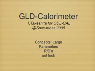
GLD Overview. May 29, 2007 Y. Sugimoto KEK. Baseline Design. Large gaseous central tracker; TPC Large-radius, high-granularity ECAL with W/Scinti sandwich structure Large-radius, medium granularity, thick (~6 l ) HCAL with Pb(Fe)/Scinti. sandwich structure

E N D
GLD Overview May 29, 2007 Y. Sugimoto KEK
Baseline Design • Large gaseous central tracker; TPC • Large-radius, high-granularity ECAL with W/Scinti sandwich structure • Large-radius, medium granularity, thick (~6l) HCAL with Pb(Fe)/Scinti. sandwich structure • Forward CAL (FCAL and BCAL) down to 5mrad • Precision Si micro-vertex detector • Si inner tracker (barrel and forward) • Si endcap tracker • Beam profile monitor in front of BCAL • Muon detector interleaved with iron plates of the return yoke • Moderate magnetic field of 3T
Baseline Design Return yoke design modified from DOD to reduce the total size of the detector and exp-hall size
Baseline Design Back-scattering from BCAL should not hit TPC directly
Detector Parameters • VTX • 6 layers (3 doublets) • R=20(18) mm – 50 mm • Fine pixel CCD as the baseline design • SIT • DSSD, 4 layers,R=9 - 30 cm • 7 discs in forward region, Z=15.5 - 101.5cm • Bunch ID capability • TPC • R=45 cm – 200 cm • Z=230 cm
Detector Parameters • ECAL • W/Scintillator/Gap = 3/2/1 mm • 33 layers • 1cmx4cm scintillator strips, w.l.s. fiber+MPPC (SiPM) readout • 2cmx2cm scintillator tile as an option • 26 X0, 1 l • HCAL • Pb(Fe)/Scinti./Gap = 20/5/1 mm • 46 layers • 1cmx20cm scintillator strips + 4cmx4cm scintillator tile, w.l.s. fiber+MPPC readout • 5.7 l • Muon detector • 8/10 layers in 4-cm gaps between 25-30 cm thick iron slabs of return yoke • X-Y scintillator strips with w.l.s.fiber+MPPC readout
Detector Parameters • PFA
Why is GLD large? • How much iron do we need? • B-field calculation based on a toy model using a FEA program was done • BR2, tECAL, tHCAL, G1, G2; fixed • Leakage field at Z=10 m was estimated as a function of B, and tFe • tFe to satisfy the leakage limit of 100G was obtained for each B
Leakage B-field • GLD-like • BR2=13.23 • tECAL=0.17m • tHCAL=1.23m • G1=G2=0.5m BZ=10m Leakage limit Andrei put the limit to 50G, but 100G can be reduced to <50G by low cost Helmholtz coil tFe (m)
Leakage B-field • LDC-like • BR2=10.24 • tECAL=0.17m • tHCAL=1.13m • G1=0.46m • G2=0.49m BZ=10m tFe (m)
Leakage B-field • SiD-like • BR2=8.06 • tECAL=0.13m • tHCAL=1.09m • G1=0.21m • G2=0.63m BZ=10m tFe (m)
B and R GLD-like LDC-like SiD-like R (m) B (T) For a given BR2, larger B (smaller RCAL) gives larger detector size
B and Cost • GLD-like detector model • Unit cost assumption • ECAL: 6.8M$/m3 • HCAL: 0.16M$/m3 • Fe: 42k$/m3 • Solenoid: 0.523x[Estore]0.662 M$ Cost (M$) B-field dependence of the total cost (CAL+Sol.+Fe) is very small B (T)
Summary • GLD is the largest detector among the three PFA detectors • GLD is the largest NOT because it has the largest inner radius of the calorimeter, but because it has the largest BR2, the thickest HCAL, and the smallest leakage field