Download
1 / 40
420 likes | 767 Vues
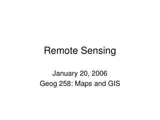
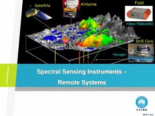
S-Polka. Remote Sensing Instruments. HIAPER Cloud radar. CSU-CHILL. NRL P-3 ELDORA. Microwave Temperature Profiler. HSRL on GV. Cloud Radar and Lidar Instruments for Sensing Aerosol and Clouds Vivek Earth Observing Laboratory NCAR, Boulder, Colorado.

E N D
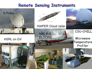
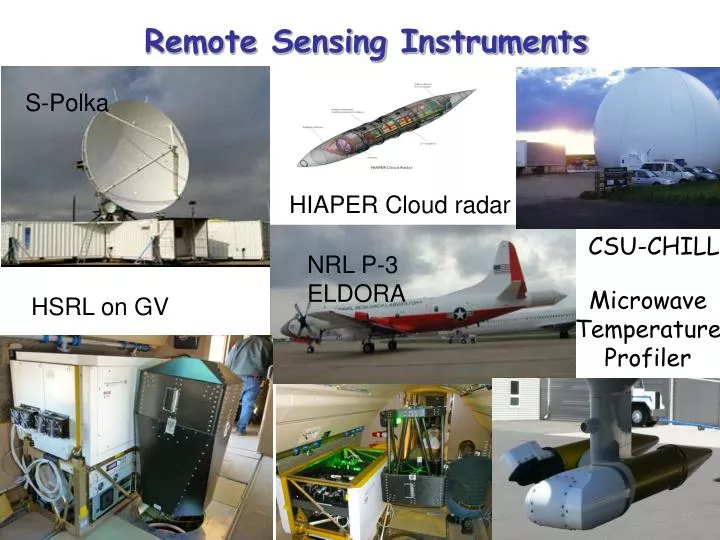
S-Polka Remote Sensing Instruments HIAPER Cloud radar CSU-CHILL NRL P-3 ELDORA Microwave Temperature Profiler HSRL on GV
Cloud Radar and Lidar Instruments for Sensing Aerosol and Clouds Vivek Earth Observing Laboratory NCAR, Boulder, Colorado NCAR maintains and deploys a suite of world-class remote sensing instruments (radars and lidars) in support of the atmospheric science community Develops innovative and state of the art “next-generation” remote sensors
Cloud: Differences in cloud parametrizations lead to variations in climate model predictions - cloud detection -optically thin clouds (-50 to -20 dBZ) - cloud fraction without reference to optical depth Cloud microphysics - Phase - size Aerosol: Aerosol type, concentration, size and shape Motivation for Observational Instruments
Liquid droplets are classified into three categories based on size Cloud droplet size < 50 mm Drizzle droplet size is between 50 and 500 mm Raindrop size > 500 mm Scientific applications Cloud radiation studies Numerical weather prediction In-flight aircraft icing Background
Cloud radiation studies Influence of cloud on earth’s radiation budget is significant (Heymesfield, 1993, Stephens 1999) Radiation impact is quantified by droplet size, liquid water content, and cloud thickness (Stephens et al, 1998) LWP= 2/3 * optical depth * effective radius e.g. For a Cloud with an optical depth of 30 and effective radius 10 mm, LWP = 200 g m-2 Even a small change in droplet size may cause large change in Cloud albedo (Slingo, 1990) Scientific Motivation
Initiation of warm rain Precipitation growth in a cumulus cloud is not well understood There is a major difference in time scales of formation of large drops between model and observation ( Knight et al., 2002) e.g. Large drops appear in cloud base well before main burst of precipitation Both observations and modeling of cloud droplet formation need to be improved Scientific Motivation (cont.)
Limitation of radar reflectivity • Problem of using radar to infer liquid water content: • Very different moments of a drop size distribution: • Reflectivity often dominated by drizzle drops ~100 mm • LWC dominated by ~10 m cloud droplets • An alternative is to use dual-wavelength radar • Radar attenuation proportional to LWC, increases with frequency • Radar reflectivity difference between two frequencies ( e.g. 3 and 35 GHz) is proportional to LWC with no size assumptions necessary • Dual-wavelength radar method can be difficult to implement in practice • Need very precise radar measurements
drizzle “transition” drizzle A million droplets of 10 mm give the same radar reflectivity as one droplet of 100 mm! A million droplets of 10 mm contain a thousand times as much water as one one droplet of 100 mm. And so: one drizzle droplet changes the reflectivity significantly without changing the liquid water content cloud droplets Ref: Herman Russchenberg, and Oleg Krasnov, 2004
Scanning, airborne, W-band Doppler radar for Gulfstream V (GV) mid-altitude jet (51kft ceiling) Phase A: system to be ready for test flights in Summer 2011 Phase B: Adds Polarimetry (H-V), pulse compression – unfunded Phase C: Adds Second wavelength (Ka-band) – unfunded Initial system design incorporates electro-mechanical infrastructure of phases B and C Radar electronics housed in un-pressurized wing-mounted pod, with data archiving and real-time display inside aircraft HCR Characteristics
Ground-based Configuration LWC ~ 0.05 – 0.1 g m-3 C-130
Rain rate estimation Matrosov, 2007, GRL
HSRL on the NCAR Gulf Stream-V Research Aircraft Technical Specifications: Wavelength: 532 nm Pulse repetition rate: 6 KHz Average power: up to 400 mW Range resolution: 7.5 m Telescope diameter: 40 cm Angular field of view 0.025 deg Filter bandwidth: 1.8 GHz
Backscatter cross section as a function of time and altitude.
GV HSRL measurements of aerosol and smoke at NCAR’s Foothills campus on September 6, 2010
Model calculation: Lidar backscatter cross section verses liquid water content
Model calculation: Median volume diameter verses Lidar Ratio
Cloud particle size estimation using radar and lidar measurements
Estimation of liquid water content using radar and lidar measurements
High Spectral Resolution Lidar and mm-wave radar • GV HSRL Designed and built by University of Wisconsin – Madison • Provides accurate measurement of optical depth, extinction and backscatter cross sections of aerosols and thin clouds • Eye-safe at the exit port (532-nm wavelength operation) • GV HSRL is already operational operation as ground based instrument • To be used to in combination with HCR to measure: • cloud fraction, precipitation rate, scattering cross sections, particle shape measurements on 1-Oct of 2008 by the arctic HSRL and MMCR Courtesy of University of Wisconsin
Lidar operates in 24/7 mode W-band radar development will be completed in 12 months Data quality - Calibration Retrieval of microphysical products from radar measurements Retrieval of aerosol and cloud products from lidar measurements Retrieval of aerosol and cloud microphysical products using both radar and lidar measurements Summary
Model calculation: Lidar backscatter cross section verses liquid water content
Aircraft icing Inflight icing is caused by impingement of supercooled droplets onto an aircraft Median volume diameter > 30 mm and LWC > 0.2 gm-3 cause hazardous icing condition (Politovich, 1989) Percentage of ice accretion ( or catch ratio) onto an airplane depend on liquid particle size Detection of droplets in a mixed phase cloud is much more challenging Scientific Motivation (cont.)
Retrieval of particle size (RES), LWC from Ka-band reflectivity and microwave Radiometer observations.
+ In-situ Radar Altitude, m Liquid water content, g m-3 Comparison of liquid water content between radar/radiometer retrievals and in-situ measurements during WISP04. In-situ measurements are from a liquid water probe on board the UND Citation research aircraft.
Liquid water content, g m-3 Size, mm Field Experiments Field Experiments Distributions of a) LWC and b) RES and MVD that were computed from in situ research aircraft measurements at various field programs. The top and bottom of each box is the 10th and 90th percentiles of the measurement set; the middle solid line is the median (50th percentile); dashed internal lines are the 25th and 75th percentiles. The numbers of samples are listed at the tops of the boxes.
Model calculation: Median volume diameter verses Lidar Ratio
Absolute Calibration Corner reflector Sea surface Noise/signal sources used to measure gain and dynamic range of the receiver Dynamic Calibration Transmitted signal continuously switched into the receiver during operation while the radar is “blind” Noise floor measurement possible periodically during aircraft turns, etc. System Calibration
Pod Based Radar System Layout Pod: Length = 158.5” Diameter = 20” Payload = 800 lbs • Extended Interaction Klystron Amplifier (EIKA) • Based on the rugged, reliable Klystron • Conduction cooled, similar to version produced for CloudSat
Liquid water content verses reflectivity K B A Compilation of various aircraft observations from Khain et al. (2008, JAMC) LWC computed from dual-wavelength (S- and Ka-band) radar