Download
1 / 21
220 likes | 323 Vues
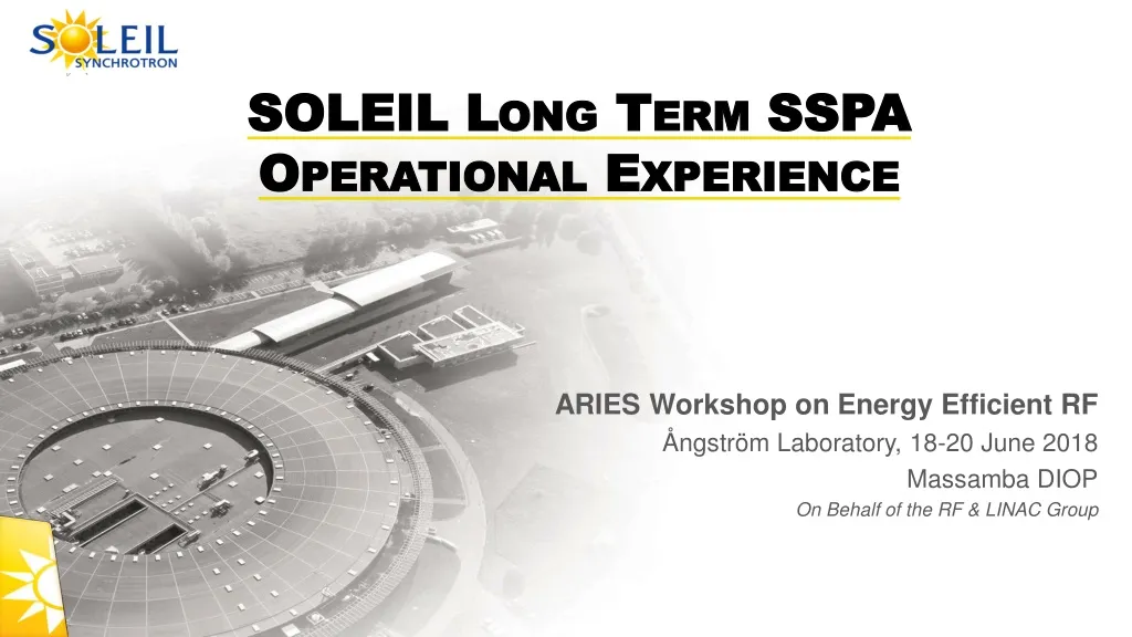
SOLEIL Long Term SSPA Operational Experience. ARIES Workshop on Energy Efficient RF Ångström Laboratory , 18-20 June 2018 Massamba DIOP On Behalf of the RF & LINAC Group. SSPA Principle.

E N D
SOLEIL Long Term SSPA OperationalExperience ARIES Workshop on Energy Efficient RF ÅngströmLaboratory, 18-20 June 2018 Massamba DIOP On Behalf of the RF & LINAC Group
SSPA Principle Combining in // a number of elementary amplifier modules (or pallets) of a few 100W (upto~ 1kW) - MOSFET (Vd = 30 - 50 V) No HV & Low phase ripple - Circulator & its load to ensure a good isolation (even a small residual VSWR can affect the MOSFET power capability !!) ≈ ≈ ≈ ≈ ≈ ≈ n1:1 n3:1 n2:1 1:n1 1:n2 1:n3 Pre- ampli xkW xkW x10kW xn3 ≈ ≈ ≈ ≈ ≈ ≈ Pre- ampli n1 Ampli modules xn2 Few kW unit Driver ampli ⇔ ⇔ The number of pre-ampli depends on the module gain xkW SOLEIL Booster first SSPA (Pnom = 35 kW @ 352 MHz) : Pmod ≈ 300 W ; n1 = 8 2.4 kW ; n2 = 8 19 kW ; n3 = 2 146 RF modules (128 Ampli + 18 Pre-A) Pout≈ 38 kW x10kW Modularity & Redundancy inherent to such a design Few 100 kW unit Few 10 kW unit x10kW
Booster Original 35 kW SSPA 300 W CW - 352 MHz amplifier module VDMOS D1029UK05 from SEMELAB (G = 11 dB, ƞ = 62 %) Circulator 600 W - 280 / 28 V dc power converter Power combiner (8 x 8 x 2) 8 dissipaters of 16 + 2* modules * Pre-amplifiers 35 kW All amplifier components were designed in house and the mass production contracted to industry In 2005, world record for a SSPA 8x300 W ~ 77000 running hours over 14 years and only one single trip from the SSPA, in August 2016, due to a loose connection on a monitoring cable (down time ~ 2.10-5and MTBF ~ 38 000 hours) ~ 1 module failure / year, without impact on the operation, thanks to the modularity and redundancy
A new 60 kW SSPA for the Booster • Booster RF system was originally designed for standard operation • The 35 kW amplifier drives a 5-cell copper cavity => VRF = 1 MV (Pdiss= 20 kW; Pbeam = 5 kW Ptot = 25 kW) • But low-ɑ operating mode suffered from a low injection efficiency (15-20%) due to the long BO bunches • Heavy safety radiation constraints • Prevents more beam lines to join this operating mode • 2nd RF station installed to increase VRF from 1 MV up to 3 MV in winter 2017-2018 • Shorter bunch length SR injection efficiency improved by a factor of ~ 2 in low-ɑ operation • Upgrade plan : • Former spare cavity installed in one straight section of the Bo ring and powered with 60 kW (VRF = 1.8 MV) • New 60 kW - 352 MHz SSPA, identical to a standard tower of our SR amplifiers • (10 dissipaters of 16 modules, built from 160 RF modules of 400 W with BLF574XR transistors and their dc-dc converters made available by the SR SSPA refurbishment) • SSPA and its associated LLRF & control (replica of the actual one) inside the Bo RF room • Increase VRF of the existing plant from 1 MV up to 1.2 MV PRF ~ 30 kW (Pbeam ~ 0) • ‘Upgraded’ Low-ɑ operating mode available for users since October 2018 • with VRF = 3 MV (SR injection efficiency = 35% instead of 18% before). • + power savings and redundancy in all other operating modes
Soleil SR 180 kW SSPA’s • Same principle as the BO one but extended to 4 towers of 45 kW: • 10 dissipaters of 18 modules per tower • 726 modules / amplifier x 4 cavities 16 towers & ~ 3000 modules LDMOS LR301 from POLYFET G : 13 dB, η: 62 % Still a world record for SSPA? Splitters 600 W - 280 Vdc / 28 Vdc A1 Combiners Amplifiers 1 & 2 (2 x 4 towers) powering the 2 cavities of Cryomodule 1 A2
SR SSPAControl Multiplexing (I x 2 x 680 mod. + Pi & Pr x 80) single µcontroller for 1 complete amplifier (4 towers) Tower T4 of Amplifier 2 Top transistor currents Pi & Pr 2.5 kW combiner Bottom transistor currents
SR SSPA’sOperationalResults MTBF & beam downtime, cumulated by the 4 SR SSPA’s over ~ 70 000 running hours in ~ 13 years • Already excellent MTBF and operational avaibility • But still perfectible • - providing some more redundancy • 1) in the ac-dc power conversion, which originally • consists in a single 500 kW rectifier per SSPA • 2) in the preamplifier stage,a failure of one of them • switching the RF off automatically • - improving the power capability of the 1st stage combiners • Cures for these “weaknesses” in our new design
180 kW SSPA’sRefurbishement • The failure rate of our original LR301 transistors remains significant, stabilized ~ 2% a year from 2012-2013. • 2 types of failures identified:- Transistor breakdown • - Damaged soldering due to thermal fatigue • Since 2013, on going refurbishment • LR301 replacement by 6th generation BLF574XR (Vd = 50V instead of 30V with better performances) • More robust transistor and lower thermal stress longer lifetime less maintenance • failure of a single « new » transistor (~ 6 years of operation) • + 7 dB transistor gain 160 modules & their dc PS are got back for the new BO SSA • Pmod increased : 315 W 450 W • Electrical power savings (efficiency : 50 % 60%) compensate the investment cost in < 3 years
180 kW SSPA’sRefurbishement • Cure the lack of redundancy in the pre-amplification stage develop a “combiner-divider” 80 80 1 1 Pre-ampli Upgrade 190kW Presentconfig : each pre-ampli drives 80 modules; if one of them fails the amplifier is stopped 24W Thanks to the combiner-divider, the failure of a pre-ampli does not affect the functioning anymore • Modification of the 2.5 kW combiners (welded screwed connections) to increase their power capability 24W 3W 3W 300W 300W 2.4kW 300W 24kW 24kW 190kW
180 kW SSPA’sRefurbishement • 12 of the 16 towers already refurbished (~ 2400 modules) rate of 5 towers a year until 2020 with SOLEIL and external resources Storage Ring RF upgrade Status Present : Now we can store 450 mA with 3 running SSPA’s or 500 mA with 3 running cavities In 2020 (end of refurbishment) : Possibility to store 500 mA with 3 running SSPA’s / cavities or 450 mA with a single cryomodule, combining 2 SSPA’s per cavity
Toward storing 450 mA using a single CM Modification of the waveguide networkto combine the power from two amplifiers into one cavity Possibility of storing the full beam current using a single CM « Magic Switch » P1+P2 OR P1 P2 depending on the post configuration P1 P2 P1 P2 CM2 CM1 Waveguidenetwork layout to power one or the other CM with 300 kW / cavfrom the 4 SSPA’s, combined by pairs Connecting 2 Magic Switches P1+P2 • The 2 Magic Switches implementedand waveguide distribution completed in end-2018 P3+P4 P1 P2 P3 P4
SOLEIL SSPA R&D Scientific Collaborations and Technology Transfers
SOLEIL R&D with352MHz SSPA’s • Development of new RF modules, based on 6th generation LDMOS (Vd = 50V) • Pmod~ 700 W, G ~ 20 dB, > 70% at 352 MHz • [ With original LR301 (28V), Pmod = 315 W, G = 13 dB, = 62 % @ 352 MHz ] • Huge improvement : Pmod x 2.2 , better performance (G , , linearity) & strong reduction in thermal stress (ΔT : - 60 °C) longer lifetime ESRF project of partly replacing its 1 MW klystrons by 150 kW SSPA’s (1 per cavity) 2009, SOLEIL transfer of technology with ELTA-AREVA 7 SSPA’s of 150 kW, built by ELTA under SOLEIL license ESRF 150 kW 352 MHz SSPA from ELTA/SOLEIL 2 towers of 75 kW ↔ 260 RF modules of 700 W BO : 4 x 150 kW SSPA’s in use since January 2012 2 trips in 7 years of operation refill postponed SR: 2 x 150 kW SSPA’s in use since October 2013 (3rd one stopped after few months due to cavity leak) 3 trips in 5 years of operation beam loss (youth problems fixed) BO + SR : ~ 1 820 transistors and not a single failure ! DC-to-RF efficiency of 58%, dc-dc converters included With new ac-dc converters (overall ac to RF) > 60%
LNLS – SOLEIL Collaboration Two SSPA’s of50 kW @ 476 MHz for LNLS (Brazilian LS) SR * with components designed by SOLEIL (400 W modules with BLF574) April 2010 in Campinas-Brazil : the SOLEIL - LNLS team, after successful tests of the amplifiers * A 2.5 kW 476 MHz SSA had already been built for the LNLS Booster
LNLS 50 kW RF plants The two 50 kW SSPA’s of the LNLS SR have run satisfactorily for > 8 years Use of SSPA’s @ 500 MHz in SIRIUS, the new LS under construction
R&D with 500 MHz SSPA at SOLEIL Increase effort on the modularity/redundancy and the efficiency * Moderate power for long lifetime (thermal stress soldering degradation) Experience feedback * + 10 pts in efficiency lead to electrical power savings over 10 years of operation ≈ full amplifier cost • New 650 W - 500 MHz modules using 6thgeneration (Vd : 50V) LDMOS BLF578 from NXP • RF output power, Pn : 650 W CW • Input return loss : - 40 dB at Pn • Unconditional stability (K >10 dB) • Gain : 17 dB at Pn (1 dB compression) • Efficiency ≈ 62 % at Pn • Gain dispersion : +/- 0.2 dB at Pn • Phase dispersion : +/- 5° at Pn Mandatory for good combining efficiency Components for gain and phase adjustments • Modular dc-dc converters + single power rectifier replaced by modular 230 Vac/ 50 Vdcconverters, in 2 kW units, 96% efficiency, voltage remote control • optimized efficiency for any operating power : • 56% (overall) @ Pmaxand 50% @ 0.6 Pmax 2 kW unit controller • Modularity brought in the preamplification stage by inserting the « divider-combiner »
500 MHz SSPA for ThomX(1) & SESAME(2) (1)ThomX : Compton X-ray source under construction in Orsay, France (2) SESAME : Jordan Synchrotron light source • Fullymodular 50V power supplies • 230 Vac/ 50 Vdcconverters, • in 2 kW units, 96% efficiency, with voltage remote control for efficiency optimization • Change from the tower to cabinet assembly, better suited with the new power supplies • Control upgrade stand-alone, self-protected and more modular • (1 µcontroler per dissipater) SESAME 80 kW SSPA (10 x 16 RF modules + 5 x 16 PS) ThomX 50 kW SSPA (6 x 16 RF modules + 3 x 15 PS) • For SESAME SR : 4 x 80 kW SSPA 1st one built by SOLEIL as a demonstrator • 3 others on the same model by SigmaPhi Electronics (SPE), SOLEIL licensee since 2014 • Status : all in operation (first pair since end 2016 and 2nd one since May 2017) • The ThomX 50 kW SSPA is also completed ; it is now being commissioned on site
1.3 GHz SSPA for LUCRECE* * RF R&D program for the French FEL project LUNEX5 • RF Power Source requirements for LUCRECE: 20 kW CW SSPA @ 1.3 GHz (SOLEIL - SPE collaboration) • ComparisonbetweenGaN and LDMOS technology Transistor performance measurements Efficiency (%) X: not measured
Other SOLEIL activities on SSPA’s • The 150 kW-500 MHz SSPA is already in the SPE catalogue • 2 x 75 kW (2 x 8 dissipaters of 16 modules) combined by • means of a wave guide to coaxial combiner, the WaCCo • R&D on VHF e-gun for LUNEX5 • 2 SSPA of 60kW@176 MHz • 800W-176MHz RF modules • (compact 800 W - 176 MHz circulators developed • in collaboration with VALVO Bauelemente) • SOLEIL upgrade towards DLSR • 6&7 BA/cell lattice z< 100 pm • Main RF: Pbeam = 250 kW at 352 MHz Re-use of our actual refurbished 180 kW SSPA’s (or part of them) + converter and control upgrade? • Harmonic system (n=4): adaptation of LUCRECE SSPA if the system is active WaCCo 2 x 80 kW WaCCo
Summary & Conclusions • SOLEIL has pioneered the use of SSPA’s in particleaccelerators • 35 kW + new 60 kW in the BO and 4 x 180 kW in the SR with outstanding operationalMTBF >> 1 year • BO RF upgrade redundancy + SR injection efficiencyimprovement in low-ɑ operating mode (~ factor of 2) • 2013: start of original transistor replacement by 6th generation LDMOS (Vd = 50 V instead of 30 V), much more robust and with higher gain and efficiency Drastic reduction in module failures, higher power capabilities and efficiency + available components for the new 60 kW BO SSPA • SR SSPA refurbishment+ “Magic switches” (+ Upgraded cavity couplers) Additional redundancy • Possibility to store full Ibeam using either a single CM or 2 CMs with only 3 running amplifiers/cavities • SOLEIL R&D on SSPA improvement of the original design in compactness, reliability and efficiency • Overall (plug to RF) efficiency ~ 65% at 352 MHz or lower frequencies, ~ 56% at 500 MHz and ~ 50% at 1.3 GHz • Scientific collaborations & technology transfers to the industry (ESRF, LNLS, ThomX, SESAME, LUCRECE, ...)