Download
1 / 47
470 likes | 475 Vues
Global Routing Method for 2-Layer Ball Grid Array Packages. Yukiko Kubo *, Atsushi Takahashi** * The University of Kitakyushu ** Tokyo Institute of Technology. Contents. Introduction Problem Definition and Strategy Global Routing Method Experiments Conclusion. Contents. Introduction

E N D
Global Routing Method for 2-Layer Ball Grid Array Packages Yukiko Kubo*, Atsushi Takahashi** * The University of Kitakyushu ** Tokyo Institute of Technology
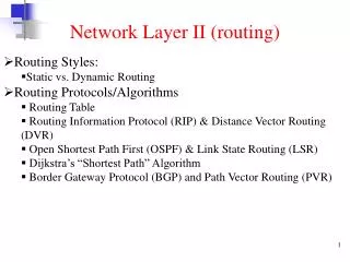
Contents • Introduction • Problem Definition and Strategy • Global Routing Method • Experiments • Conclusion
Contents • Introduction • Problem Definition and Strategy • Global Routing Method • Experiments • Conclusion
Introduction • Old package design • Circuits were small • Number of I/O terminals of packages was small -> Terminals were put on perimeter of package board • Radial routing • Manual design or simple automatic design
Introduction Ball Grid Array • Recent package design • Circuits are large • Number of I/O terminals of packages is large • Ball Grid Array (BGA) • Routing design is difficult • Reduction of design term • Routing automation
Previous Works for BGA Package Design • Net generation and global routing (single layer) • Yu and Dai [ICCAD95] • Shibata etc. [JIEP97](in Japanese) • Layer Assignment and single layer routing • Tsai, Wang and Chen [TCAD98] • Chen, Chen, Tsai and Chen [ICCD99] Existing algorithms are for single layer routing Global routing method for 2-layer BGA packages is proposed
Contents • Introduction • Problem Definition and Strategy • Global Routing Method • Experiments • Conclusion
Our target Ring wire for plating • Target: 2-layer BGA package with plating leads • Plating lead: a wire connecting outer ring to plate wires • Finger (on layer1): connecting BGA board and chip • Ball (on layer2): connecting BGA board and PCB • Net: 2-terminal (a finger and a ball) with plating lead chip finger ball Plating lead via Route on layer1 finger via ball Route on layer2
Via assignment Vias are on grid array: Radius of vias are large for ball pitch = At most one via is allowed between four adjacent balls
1 2 3 4 5 6 1 2 3 45 6 1 2 3 45 6 4 5 5 4 5 4 2 2 2 1 1 1 3 3 3 6 6 6 Routing strategy: Monotonic routing • Monotonic Routing: • never snakes in horizontal direction • crosses any horizontal line at most once Monotonic routing Non-monotonic routing
1 2 3 4 5 6 4 5 2 1 3 6 Condition for Monotonic Routing • Monotonic routing is possible if and only if via assignment is monotonic • Monotonic via assignment: • Net labels of vias on each row are subsequence of net labels of fingers • In monotonic via assignment, • Monotonic global routes are determined uniquely • Global routing = Monotonic via assignment
11 4 11 10 4 5 10 1 6 5 7 13 1 2 6 7 9 13 2 0 3 8 12 9 14 0 3 8 12 14 Routing Strategy: Routes on Each Layer • Layer1: Monotonic routes with plating tales • Via assignment is monotonic • Global routes are determined uniquely • Layer2: Short routes • Each via is put near corresponding ball 0, 1, … , 14 Layer2 Layer1
11 4 11 10 4 5 10 1 6 5 7 13 1 2 6 7 9 13 2 0 3 8 12 9 14 0 3 8 12 14 Evaluation of Routes • Via assignment is monotonic -> Global routes can be determined uniquely • Global routes are evaluated by via assignment • Evaluation: wire length (layer1), wire length (layer2) and wire congestion 0, 1, … , 14
11 4 11 10 4 5 10 1 6 5 7 13 1 2 6 7 9 13 2 0 3 8 12 9 14 0 3 8 12 14 Evaluation: Wire Length • Monotonic routes • If wire length is long, =routes snake =routes cross vertical grid line Wire length (Layer1): the number of crosses of vertical grid line and global routes 2 5 Len:2 Len:0
Evaluation: wire length Wire Length(Layer2): Manhattan distance between a ball and a via 2 5 5 Len:2 5 Len:1 2 2
Congestion: 5 Congestion: 3 11 4 11 10 4 5 10 1 6 5 7 13 1 2 6 7 9 13 2 0 3 8 12 9 14 0 3 8 12 14 Evaluation: Wire congestion • Routing failure occurs = Congestion is dense = Congestion is not ballanced Difference of congestion: |3-5|=2 Congestion between adjacent 2 vias: Reciprocal of wire pitch Congestion evaluation: Sum of difference of adjacent congestion
Problem Definition 2-Layer BGA Package Routing • Input: 2-terminal nets (pair of a ball and a finger) • Output: Global routes including vias • Objective: To minimize Cost=a*wire length(layer1) + b*wire length(layer2) + c*wire congestion • Constraints: • Monotonic via assignment • Plating leads
Contents • Introduction • Problem Definition and Strategy • Global Routing Method • Experiments • Conclusion
Routing Optimization Approach • Greedy algorithm • Give initial via assignment • Select via-assignment modification with maximum gain under monotonic constraint • If maximum gain > 0, apply the modification and go to 2
Routing Optimization Approach • Greedy algorithm • Give initial via assignment • Select via-assignment modification with maximum gain under monotonic constraint • If maximum gain > 0, apply the modification and go to 2
4 11 10 1 6 5 7 13 2 0 3 8 12 9 14 Initial via assignment • Vias are generated according to ball sequences • Each via sequence is divided into monotonic sub-sequences • Vias of sub-sequences for same ball sequence are put on different rows of via grid array 0, 1, … , 14 4 11 10 1 6 5 7 13 2 0 3 8 12 9 14
4 11 10 1 6 5 7 13 2 0 3 8 12 9 14 Initial via assignment • Vias are generated according to ball sequence • Each via sequences are divided into monotonic sub-sequences • Vias of sub-sequences for same ball sequence are put on different rows of via grid array Vias of sub-sequences in different ball sequences can share same row of via grid array 0, 1, … , 14 11 4 10 5 1 6 7 13 2 9 0 3 8 12 14
11 4 11 10 4 5 10 1 6 5 7 13 1 2 6 7 9 13 2 0 3 8 12 9 14 0 3 8 12 14 Initial via assignment • Vias are generated according to ball sequence • Each via sequences are divided into monotonic sub-sequences • Vias of sub-sequences for same ball sequence are put on different rows of via grid array Vias of sub-sequences in different ball sequence can share same row of via grid array 0, 1, … , 14 11 4 10 5 1 6 7 13 2 9 0 3 8 12 14
Routing Optimization Approach • Greedy algorithm • Give initial via assignment • Select via-assignment modification with maximum gain under monotonic constraint • If maximum gain > 0, apply the modification and go to 2
Via assignment modification • Modification patterns • 2-via exchange • 3-via rotation • Sequential via movement
2-via exchange, 3-via rotation • 2-via exchange: • Adjacent 2 vias are exchanged • 3-via rotation: • 3 vias on a unit grid are rotated u u i j k i l k j l d d 2-via exchange 3-via rotation
4 11 10 1 6 5 7 13 2 0 3 8 12 9 14 Sequential via movement • Vias are moved to their adjacent grid one by one without overlaps 0, 1, … , 14 11 4 5 10 1 2 6 7 9 13 0 3 8 12 14
Complexity • Modification with maximum gain • enumerating all modifications • calculating the gain of them • Complexity to obtain modification with maximum gain (n: number of nets) • 2-via exchange: O(n) • 3-via rotation: O(n) • Sequential via movement: O(n2) • Total: O(n2)
Routing Optimization Approach • Greedy algorithm • Give initial via assignment • Select via-assignment modification with maximum gain under monotonic constraint • If maximum gain > 0, apply the modification and go to 2
Contents • Introduction • Problem Definition and Strategy • Global Routing Method • Experiments • Conclusion
Experiments • Proposing method is implemented by C++ • CPU 3GHz, 1GB memory • Cost function: • length(layer1) + length(layer2) + congestion ( a = b = c = 1 ) • Comparison: • ALL (Proposing method): 2-via exchange, 3-via rotation, and sequential via movement • SEQ: Sequential via movement only
Experimental results Calculation Time (s) • ALL generates better routes than SEQ • ALL takes much more time than SEQ • Tradeoff between quality of solution and calculation time
Experimental result (data3) Length(layer1): 252 → 53 Length(layer2): 160 → 193 Congestion: 414.3 → 129.8 Time(s): 1.90 (sec)
Contents • Introduction • Problem Definition and Strategy • Global Routing Method • Experiments • Conclusion
Conclusion • Global routing method for 2-layer BGA packages was proposed • Monotonic routing was introduced • Global routing method by monotonic via assignment was proposed • The method gives initial via assignment and improve it by via assignment modification • Experimental results • Our method generates good global routes • Tradeoff between quality of solution and calculation time
Future work • Reduction of calculation time without degrading solution • Accurate design rule consideration for both layer1 and layer2 • Plating leads planning • Whether is the plating lead of each net routed on Layer1 or Layer2?
BGA Package Design • Consideration • Multi-layer routing • Obstacles • Plating lead • Chip scale package • Multi-chip on board • Electrical effects die Au bonding wire bonding finger board solder ball
4 11 10 1 6 5 7 13 2 0 3 8 12 9 14 Evaluation: Wire length on layer1 11 len: 1 4 5 10 1 2 6 7 9 13 len: 3 0 3 8 12 14
Routes distribution • Many obstacles on layer2 • For short routes • Little obstacles on layer1 • For long routes • Plating leads is on layer1 Layer2 Layer1
11 5 10 11 4 1 2 7 9 13 4 4 11 11 10 10 4 5 10 6 0 3 8 12 14 1 1 6 6 5 5 7 7 13 13 1 2 6 7 9 13 2 2 0 0 3 3 8 8 12 12 9 9 14 14 0 3 8 12 14 Sequential via movement 0, 1, … , 14 0, 1, … , 14 Layer1: Layer2: Congestion:
Local change of the cost • Local change of cost is possible to calculate if • Adjacent vias of the target via are known • Two previous vias and a next via in the movement are known • Sum of local change of cost = gain k u i j i * k j l l d d The direction of movement is restricted to {right, left} or {above, below}
Cost graph Nodes: target via and two previous vias Edges: the direction of next via j, k, u u i j k l j, k, l i, j, k d j, k, d
Cost graph Nodes: target via and two previous vias Edges: the direction of next via a j, k, u k, u, a u b … j, k, l i j k l c k, u, b i, j, k d j, k, d Weight of edges are local change of cost k, l, b
Cost graph • Directed acyclic graph • Calculate longest path • Longest path = sequential movement with maximum gain • Sequential via movement with maximum via is selected • For all starting nodes, • Generate cost graph • Search longest path • Select path with maximum gain among all
Experimental results • Comparison • ALL: • Proposing method • SEQ • sequential via movement only • Via movement starts with via of large cost
Our Strategy • Strategy: • Layer1: Monotonic routes with plating leads • Layer2: Short routes Layer2 Layer1