Download
1 / 21
210 likes | 357 Vues
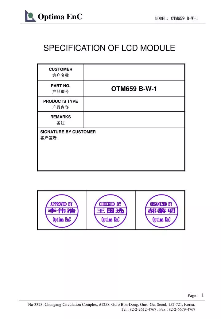
APPROVED BY. CHECKED BY. ORGANIZED BY. 李伟浩. 王国选. 郝黎明. Optima EnC. Optima EnC. Optima EnC. SPECIFICATION OF LCD MODULE. LCM System. LCD Type. 1. S - STN. D - D FSTN. F - FSTN. Viewing Angle. 2. U - Upper 12:00. D - Lower 6:00. O - Others. Display Mode. 3.

E N D
APPROVED BY CHECKED BY ORGANIZED BY 李伟浩 王国选 郝黎明 Optima EnC Optima EnC Optima EnC SPECIFICATION OF LCD MODULE
LCM System LCD Type 1 S - STN D - DFSTN F - FSTN Viewing Angle 2 U - Upper 12:00 D - Lower 6:00 O - Others Display Mode 3 Yellow Green positive Blue Negative Grey positive W - FSTN negative FSTN positive Polarizer Mode 4 Reflective Transflective Transmissive Connector 5 Zebra Heat sealed Pin Thickness of Glass 6 0.4mm 1.1mm 0.55mm 0.7mm Backlight Mode: 7 LED CCFL Backlight Color 8 Blue Amber Yellow Green White Red Without backlight Temperature Grade 9 Super wide temperature Normal temperature Wide temperature CG-ROM 10 01 for English + Japanese language
CONTENTS • FEATURES …………………………………………….........................…. • MECHANICAL SPEC ………………...………………………………..….. • ABSOLUTE MAXIMUM RATING .………. …………..……………………. • ELECTRICAL CHARACTERISTICS ……… …..………………………… • ELECTRO-OPTICAL CHARACTERISTICS ..…………...……..……….. • BLOCK DIAGRAM ..………………………………………………………… • POWER SUPPLY …………………..………………………………………. • TIMIING DIAGRAM ……………………………….…..………….……..... • AC CHARACTERISTICS …………………………………………………. • INSTRUCTION SET .……..…………….………………………..………... • INITIALIZATION SEQUENCE ……………………………….………….. • FONT TABLE …..…….……..……………………………………….……. • OUTLINE DRAWING .....……..…………………………….……………….. • INTERFACE .....……..…………………………………………………. ….. • QC/QA PROCEDURE ......……………………………...………………... • RELIABILITY .……...………………………………………………..……..... • 17. HANDING PRECAUTIONS ………………………………………………… 5 5 6 6 8 9 9 10 11 12 13 14 15 16 17 18 19
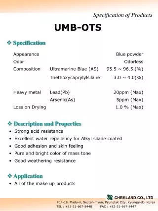
1. FEATURES 16 Characters * 2 Lines STN(Blue) Negative Transmissive LED/5.0V(White) 6 o’clock -20 to 70℃ -30 to 80℃ S6A0069 or Eequivalence Single power 1/16 duty, 1/5 bias COB (Chip On Board) 6800 4/8-bit parallel PIN • Display construction ………… • Display mode …………………… • Display type …………………… • Backlight ………………………… • Viewing direction ……………… • Operating temperature ………… • Storage temperature …………… • Controller ……………………… • Driving voltage ………………… • Driving method …………………… • Type ……………………………… • Number of data line …………… • Connector ………………………… 2. MECHANICAL DATA
3. ABSOLUTE MAXIMUM RATINGS (TA = 25 ,Vss=0V) 4. ELECTRICAL CHARACTERISTICS (VDD 4.5 to 5.5V , TA = 25 )
D1 D2 K A 4.1 LED ELECTRICAL/OPTLCAL CHARACTERISTICS 4.2LED ABSOLUTE MAXIMUM RATINGS 4.2.1 LED ARRAY BLOCK DIAGRAM ( LED DICE 1×2= 2 dices ) 4.2.2 LED POWER SOURCE
5. ELECTRO-OPTICAL CHARACTERISTICS Note 1: Definition of Contrast Ratio “K” Note 2: Definition of Optical Response Time Note 3: Definition of Viewing Angle
R7 LEDA BACKLIGHT LEDK 6. BLOCK DIAGRAM CONTROLLER: S6A0069 OR Eequivalence COM 9-16 VSS COM 1-8 LCD 16 character×2 line VDD VEE RS R/W E SEG 1-40 SEG 41-80 D0~D7 4 SEGMENT DRIVER 7. POWER SUPPLY VEE
8. TIMING DIAGRAM • WRITE OPERATION • READ OPERATION
9. AC CHARACTERISTICS • WRITE MODE • READ MODE
11. INSTRUCTION SET COMMAND COMMAND CODE COMMAND CODE E-CYCLE fosc=250KHz RS R/W DB7 DB6 DB5 DB4 DB3 DB2 DB1 DB0 SCREEN CLEAR 0 0 0 0 0 0 0 0 0 1 Screen Clear, Set AC to 0 Cursor Reposition 1.64ms CURSOR RETURN 0 0 0 0 0 0 0 0 1 * DDRAM AD=0, Return, Content Changeless 1.64ms INPUT SET 0 0 0 0 0 0 0 1 I/D S Set moving direction of cursor, Appoint if move 40us DISPLAY SWITCH 0 0 0 0 0 0 1 D C B Set display on/off,cursor on/off, blink on/off 40us SHIFT 0 0 0 0 0 1 S/C R/L * * Remove cursor and whole display,DDRAM changeless 40us FUNCTION SET 0 0 0 0 1 DL N F * * Set DL,display line,font 40us CGRAM AD SET 0 0 0 1 ACG Set CGRAM AD, send receive data 40us DDRAM AD SET 0 0 1 ADD Set DDRAM AD, send receive data 40us BUSY/AD READ CT 0 1 BF AC Executing internal function, reading AD of CT 40us CGRAM/ DDRAM DATA WRITE 1 0 DATA WRITE Write data from CGRAM or DDRAM 40us CGRAM/ DDRAM DATA READ 1 1 DATA READ Read data from CGRAM or DDRAM 40us I/D=1: Increment Mode; I/D=0: Decrement Mode S=1: Shift S/C=1: Display Shift; S/C=0: Cursor Shift R/L=1: Right Shift; R/L=0: Left Shift DL=1: 8D DL=0: 4D N=1: 2R N=0: 1R F=1: 5x10 Style; F=0: 5x7 Style BF=1: Execute Internal Function; BF=0: Command Received DDRAM: Display data RAM CGRAM: Character Generator RAM ACG: CGRAM AD ADD: DDRAM AD & Cursor AD AC: Address counter for DDRAM & CGRAM E-cycle changing with main frequency. Example: If fcp or fosc=270KHz 40us x 250/270 =37us
Parts QA Dept. LCD Mfg. Dept. LCM QA Dept. Parts 1. Function & Appearance & Dimension: Sample Test 2. Reliability: Random Sampling Parts Acceptance Inspection Soldering Soldering Inspection Soldering Condition 1. Dimension: Sample Test 2. Function: 100% Inspection LCM Assembling -10~70℃ (1 Cycle=6 Hrs). 2 Cycle: 100% Inspection Heat Cycle Aging High Temp. Test Function & Appearance: 100% Inspection (ex. 50℃) 1. Function & Appearance: 100% Inspection 2. Dimension: Random Sampling Inspection Package Condition & Label: 100% Inspection Packaging Outgoing Inspection 1. Function,Appearance & Dimension: Random Sampling 2. Package Product & Label: Random Sampling 3.Electro-optical Characteristic: 100% Inspection 4. Reliability: Random Sampling Storage/Shipping 15. QC/QA PROCEDURE
16. RELIABILITY • Operating life time: • Longer than 50000 hours (at room temperature without direct irradiation of sunlight) • Reliability Characteristics:
17. Handling Precautions 1. Limitation of Application: Optrex products are designed for use in ordinary electronic devices such as business machines, telecommunications equipment,measurement devices and etc. Please handle the products with care. (see below) Optrex products are not designed,intended ,or authorized for use in any application which the failure of the product could result in a situation where personal injury or death may occur . these applications include, but are not limited to . life-sustaining equipment,nuclear control devices , aerospace equipment , devices related to hazardous or flammable materials , etc.[If Buyer intends to purchase or use the Optrex Products for such unintended or unauthorized applications , Buyer must secure prior written consent to such use by a responsible officer of Optrex Corporation.]Should Buyer purchase or use Optrex Products for any such unintended or unauthorized application [ without such consent ].Buyer shall indemnify and hold Optrex and its officers. employees. subsidiaries, affiliates and distributors harmless against all claims, costs, damages and expenses , and reasonable attorney’s fees,arising out of , directly or indirectly, any claim of personal injury or death associated with such unintended or unauthorized use, even if such claim alleges that Optrex was negligent regarding the design or manufacture of the part. 2.Industrial Rights and Patents Optrex shall not be responsible for any infringement of industrial property rights of third parties in any country arising out of the application or use of Optrex products, except which directly concern the structure or production of such products. No Press and Shock! Don’t Swallow or Touch Liquid Crystal! Don’t not Scratch! No DC Voltage to LCD! - 68 -
Don’t Press the Metallic Frame and Disassemble the LCM Slowly Peel Off Protective Film! Avoid Static Electricity! Wear Gloves While Handing! Keep Away From Extreme Heat and Humidity! Use Alcohol to Clean Terminals!
Don’t Drop Water on LCD! Precaution in Soldering LCD Module Basic instructions: Solder I/O terminals only. Use soldering iron without leakage. (1)Soldering condition to I/O terminals Temperature at tip of the iron: 280±10℃ Soldering time: 3~4 sec. Type of solder: Eutectic solder (containing colophony-flux) *Please do not use flux because it may soak into LCD Module or contaminate it. *It is preferable to peel off protective film on display surface after soldering I/O terminals is finished. (2)Remove connector or cable *When you remove connector or cable soldered to I/O terminals, please confirm that solder is fully melted. If you remove by force, electrodes at I/O terminals may be damaged(or stripped off). *It is recommended to use solder suction machine. Long-term Storage If it is necessary to store LCD modules for a long time, please comply with the following procedures. If storage condition is not satisfactory, display(especially polarizer) may be deteriorated or soldering I/O terminals may become difficult(some oxide is generated at I/O terminals plating). 1.Store as delivered by Optrex 2.If you store as unpacked,put in anti-static bag,seal its opening and store where it is not subjected to direct sunshine nor fluorescent lamp. 3.Store at temperature 0 to +35℃ and at low humidity.Please refer to our specification sheets for storage temperature range and humidity condition. Long-term Storage Please use power supply with built-in surge protection circuit.