Download
1 / 1
20 likes | 254 Vues
CATIA-GDML Geometry Builder. S. Belogurov 1,2 (belogurov@itep.ru), Yu. Berchun 2 , A. Chernogorov 1 , P. Malzacher 3 , E. Ovcharenko 1,2 , A. Semennikov 1. 1- Institute for Theoretical and Experimental Physics (ITEP), Moscow, Russia

E N D
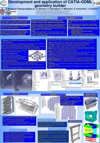
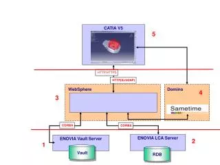
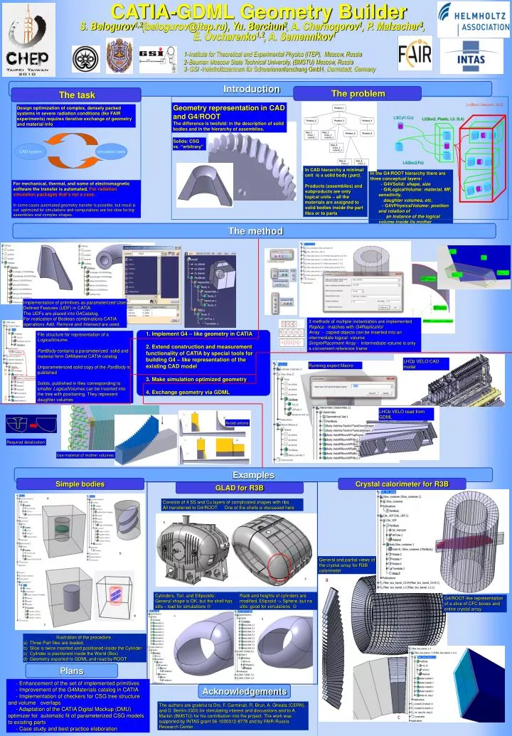
CATIA-GDML Geometry Builder S. Belogurov1,2(belogurov@itep.ru), Yu. Berchun2, A. Chernogorov1, P. Malzacher3, E. Ovcharenko1,2, A. Semennikov1 1- Institute for Theoretical and Experimental Physics (ITEP), Moscow, Russia 2- Bauman Moscow State Technical University, (BMSTU) Moscow, Russia 3- GSI - Helmholtzzentrum für Schwerionenforschung GmbH, Darmstadt, Germany Introduction The problem The task L1(Box1,Vacuum ,3L2) Geometry representation in CAD and G4/ROOT The difference is twofold: in the description of solid bodies and in the hierarchy of assemblies. Design optimization of complex, densely packed systems in severe radiation conditions (lke FAIR experiments) requires iterative exchange of geometry and material info L3(Cyl1,Cu) L2(Box2, Plastic , L3, 2L4) Solids: CSG vs. “arbitrary” CAD system simulation tools L4(Box3,Fe) In CAD hierarchy a minimal unit is a solid body (part). Products (assemblies) and subproducts are only logical units – all the materials are assigned to solid bodies inside the part files or to parts • In the G4/ROOT hierarchy there are three conceptual layers: • - G4VSolid: shape, size • - G4LogicalVolume: material, MF, sensitivity, • daughter volumes, etc. • - G4VPhysicalVolume: position and rotation of • an instance of the logical volume inside its mother For mechanical, thermal, and some of electromagnetic software the transfer is automated.For radiation simulation packages that’s not a case. In some cases automated geometry transfer is possible, but result is not optimized for simulations and computations are too slow for big assemblies and complex shapes. The method Implementation of primitives as parameterized User Defined Features (UDF) in CATIA. The UDFs are placed into G4Catalog. For realization of Boolean combinations CATIA operations Add, Remove and Intersect are used. 3 methods of multiple instantiation are implemented Replica - matches with G4ReplicaVol Array - copied objects can be inserted into an intermediate logical volume SimplePlacement Array - intermediate volume is only a convenient reference frame File structure for representation of a LogicalVolume. PartBody contains a parameterized solid and material form G4Material CATIA catalog. Unparameterized solid copy of the PartBody is published Solids, published in files corresponding to smaller LogicalVolumes can be inserted into the tree with positioning. They represent daughter volumes 1. Implement G4 – like geometry in CATIA2. Extend construction and measurement functionality of CATIA by special tools for building G4 – like representation of the existing CAD model3. Make simulation optimized geometry4. Exchange geometry via GDML LHCb VELO CAD model Running export Macro M d d d LHCb VELO read from GDML Avoid unions Required detalization Use material of mother volumes Examples Simple bodies Crystal calorimeter for R3B GLAD for R3B Consists of 4 SS and Cu layers of complicated shapes with ribs. All transferred to G4/ROOT. One of the shells is discussed here General and partial views of the crystal array for R3B calorimeter Cylinders, Tori, and Ellipsoids: General shape is OK, but the shell has slits – bad for simulations Radii and heights of cylinders are modified, Ellipsoid -> Sphere, but no slits: good for simulations G4/ROOT-like representation of a slice of CFC boxes and entire crystal array • Illustration of the procedure. • Three Part files are loaded. • Slice is twice inserted and positioned inside the Cylinder • Cylinder is positioned inside the World (Box) • Geometry exported to GDML and read by ROOT Plans - Enhancement of the set of implemented primitives - Improvement of the G4Materials catalog in CATIA - Implementation of checkers for CSG tree structure and volume overlaps - Adaptation of the CATIA Digital Mockup (DMU) optimizer for automatic fit of parameterized CSG models to existing parts - Case study and best practice elaboration Acknowledgements The authors are grateful to Drs. F. Carminati, R. Brun, A. Gheata (CERN), and D. Bertini (GSI) for stimulating interest and discussions and to A. Markin (BMSTU) for his contribution into the project. The work was supported by INTAS grant 06-1000012-8778and by FAIR-Russia Recearch Center.